31.1.8. Helical-Internal Gear
Created from a predefined data file.
Edited from a predefined data file.
Exported from a predefined data file.
Imported from a predefined data file.
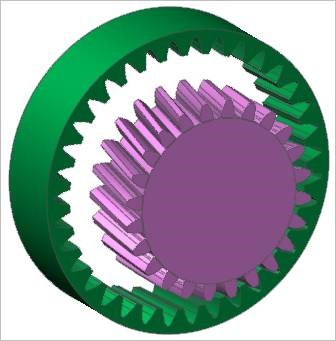
Figure 31.43 Helical-Internal Gear assembled with a helical gear
31.1.8.1. Properties
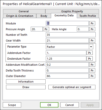
Figure 31.44 Helical Internal Gear property page [Geometry Data page]
The Helical Internal Gear property page is shown in Figure 31.44. The parameters are explained below. In order to understand the geometry, refer to Geometric Entities.
Module: Enters the module of the gear.
Pressure Angle: Enters the pressure angle of the gear.
Helix Angle: Enters the helix angle of the gear.
Number of Teeth: Enters the number of teeth. The maximum number of teeth of gear is 400.
Gear Width: Enters the width of the gear.
Parameter Type: two methods are supported to define the Addendum and Dedendum.
Factor: Defines the addendum and dedendum as factors. For more information, click here.
Addendum Factor: Enters the factor to define the addendum.
Dedendum Factor: Enters the factor to define the dedendum.
Addendum Radius & Whole Depth: Defines the addendum and dedendum as addendum radius and whole depth. For more information, click here.
Addendum Radius: Enters the addendum radius for the gear.
Whole Depth: Enters the whole depth as summation for the addendum and dedendum.
Addendum Modification Coef.: Enters the coefficient to define the addendum.
Delta Tooth Thickness: Enters the delta value to define the tooth thickness. For more information, click here.
Information: Shows the calculated values for Pitch Radius, Tip Radius, Base Radius, Root Radius, and Circular Tooth Thickness.
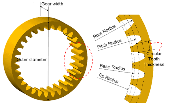
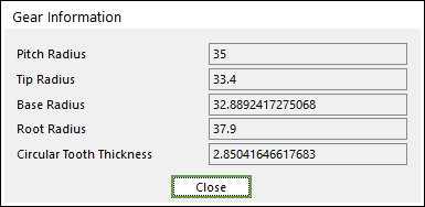
Figure 31.45 Gear Information dialog box
Draw: All data must be defined with respect to the tooth marker. You can move points graphically by using the mouse directly.
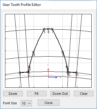
Figure 31.46 Gear Tooth Profile Editor dialog box
Generate optimal arc segment: In order to apply the modification of tooth, this button should be clicked.