28.4.2.3. Grouser Contact
It is helpful for the user to see the geometric entity of track links when defining the grouser contact. Grouser contact is defined with sphere-to-sphere contact. The determination of the sphere location depends not only on the link geometric entity but also on the bushing deformation between links, which affects track shoe spacing. The Distance parameter is used to include the effect of bushing deformation when is defining the sphere positions. When applying a new distance value the track geometric entity is adjusted on the screen so that users have visual feedback on track spacing. Distance parameter is used only during the grouser contact definition and does not affect the simulation.
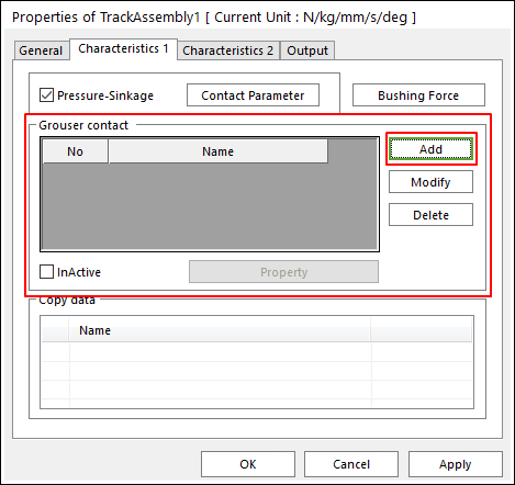
Figure 28.92 Assembly Information property page [Characteristic 1 page]
Add: In order to define Grouser sphere to sphere contact, some functions are supported as follows.
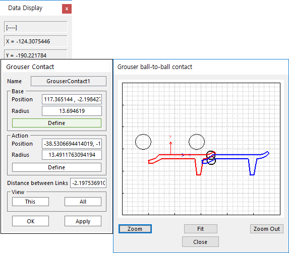
Figure 28.93 Grouser Contact dialog box
Name: Shows the grouser contact name.
Base: Defines the base contact geometry as Position and Radius.
Action: Defines the action contact geometry as Position and Radius.
Define: The use can create a sphere geometry by clicking a mouse in Draw dialog box. Selects a point to define the center of the sphere geometry and then defines a radius.
Distance between Links
View: Shows sphere geometries defined in this grouser contact or all grouser contact
Modify: Modifies the definition of sphere geometry entities for the selected grouser contact.
Delete: Deletes the selected grouser contact.
Property: Defines characteristic values for the selected grouser contact between two sphere geometry entities.
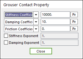
Figure 28.94 Grouser Contact Property dialog box
InActive: Checks the active or inactive grouser contact entities.
Example
The user would like to prevent the track from bending back by using Grouser Contact. The yellow sphere of track link A is fixed and users would like to determine the sphere position of link B. Assume that bending back phenomena is often generated when bushing deformation is almost zero. The user inputs the distance value of 0 and can easily the position of red sphere.
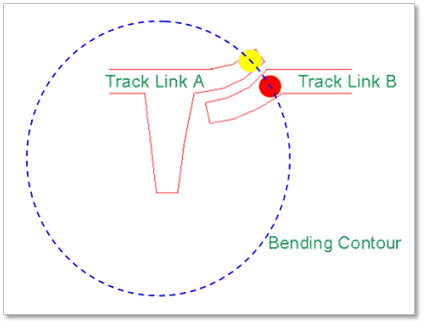
Figure 28.95 Track link geometric entities at distance zero
Assume that the bending back contact often occurs when bushing deformation amount is 10 mm. By setting the distance parameter to 10mm, the user can see the geometric entities of track links as shown in Figure 28.96. Users can position the blue sphere easily while considering the 10mm distance and its effect on the bending contour geometric entity.
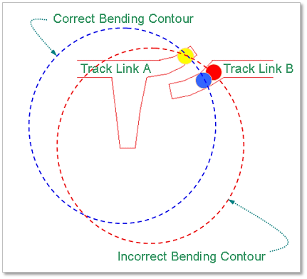
Figure 28.96 Track link geometric entities at distance 10 mm
Thus the user can accurately defining grouser contact while considering the operating conditions by referencing the correct spacing of track shoes under operating tension.
Grouser Contact is to define a ball to ball contact between adjacent track links, as shown in Figure 28.97.
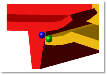
Figure 28.97 Grouser contact