13.1.1. Component Group
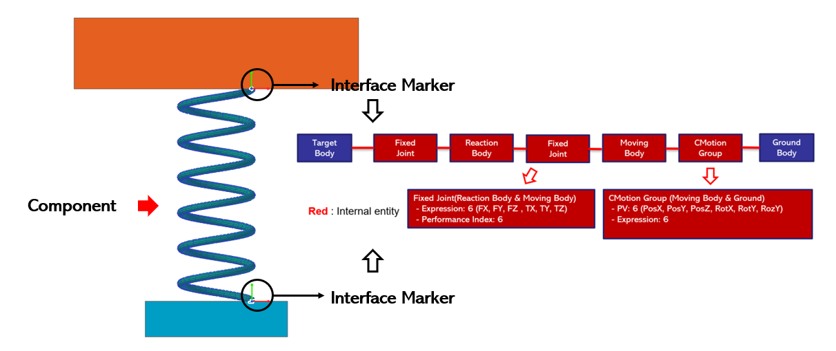
Figure 13.2 Entity Created internally in Component Group
13.1.1.1. Modeling Options
The user can create a component group as follows.
Body, MultiMarker
Body: Selects a body to define the component of FFlex body.
MultiMarker: Select a marker of FFlex body using interface of component. The first selected marker is the reference marker.
13.1.1.2. Properties
The property dialog of the component group is used with the meta model file created after the component meta model is all finished. For the Component Meta Model process, click here. For the PMM process, click here.
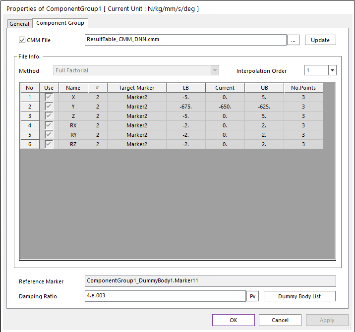
Figure 13.3 Component Group Dialog
CMM File: Import the CMM file.
Update: Updates the information in the selected file.
File Info: It shows the information of the imported file. (Selected design variable, Lower/Upper boundary, Current Value) which is updated.
Reference Marker: Shows reference marker.
Damping Ratio: Input the damping ratio for meta model force.
Dummy Body List: Dummy body is set up to make up for the inertia effect in place of the swapped component group. The initial 3 dummy bodies are set automatically. The first two are dummy bodies with basic mass and moment of inertia at the interface points. The third dummy body is defined at the CM position of the swapped component group and has mass and moment of inertia of the component group. Dummy bodies at interface points are basically used and the use of the rest of the dummy bodies depends on the user’s choice.
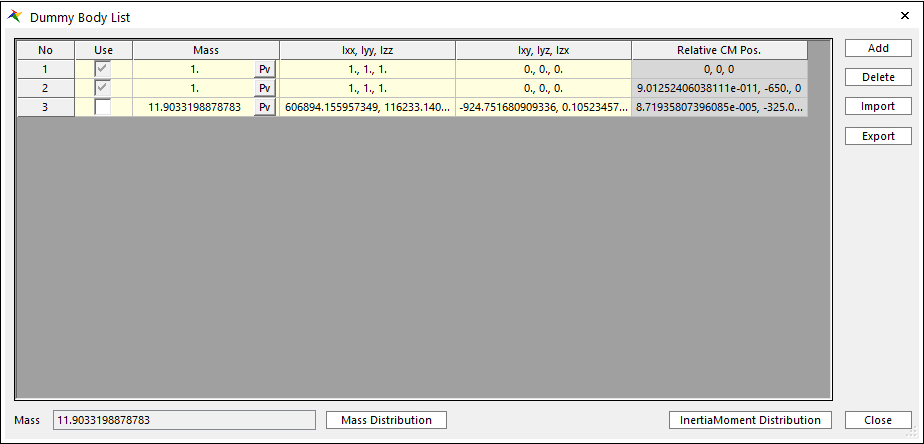
Figure 13.4 Dummy Body List
Use: If this option is checked, it means that the dummy body will be used which is connedted to each interface points. At least one dummy body is created by default at the location of the interface point.
Mass: Define mass of dummy body.
Ixx, Iyy, Izz: Define the moment of inertia of dummy body. (Ixx, Iyy, Izz)
Ixx, Iyy, Izz: Define the moment of inertia of dummy body. (Ixy, Iyz, Izx)
Relative CM Pos.: Define dummy body position relative to reference frame.
Mass Distribution: Distribute mass of component group to the each dummy body. It allocates half of mass of component group for the dummy bodies at interface points and half to the rest of dummy bodies.
Inertia Distribution: Distribute moment of inertia of component group to the each dummy body. The moment of inertia for the component group is divided according to the mass ratio and assigned to each dummy body.
Note
If users use the last row of Dummy Body List, 1/2 of total mass and inertia are entered in the mass center, and the remaining values are divided into the interface.
Add: Add row.
Delete: Delete row.
Import: Import dummy body information.
Export: Export dummy body information in xml file.
Note
All data in Dummy Body List is expressed with respect to reference frame same as orientation of 1st interface marker.