37.3. Chain Coupler
A chain coupler is consisted of bodies connected with screw couplers. It shows the force and torque to bodies by the revolution of bodies.
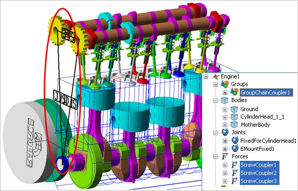
Figure 37.14 Chain Coupler
Step to create a Chain Coupler Group
Click the Chain_Coupler icon of the Engine group in the Engine tab.
Select the connecting bodies with a chain coupler. (To select the body in the inner subsystem, click the desired body with pressing the shift key). Refer to Assembly method of chain coupler.
Click the right mouse button and choose Finish Operation.
The user can see the following dialog box. If the user clicks Connection in Figure 37.15, the Screw Coupler Property Sheet dialog box appears. In this dialog box, the user can confirm and define the force parameter. For more information, refer to Characteristic Page in Contact of General Entities.
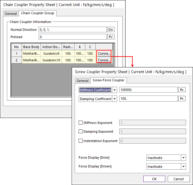
Figure 37.15 Chain Coupler Property Sheet dialog box
Normal Direction: Select the normal direction of chain coupler.
Preload: Define the pretension.
Basic Concept of Chain Couplers
A set of Chain Couplers: Setting one Multi_Axes_Chain_Coupler, two set of screw coupler is attached between two bodies as follows.
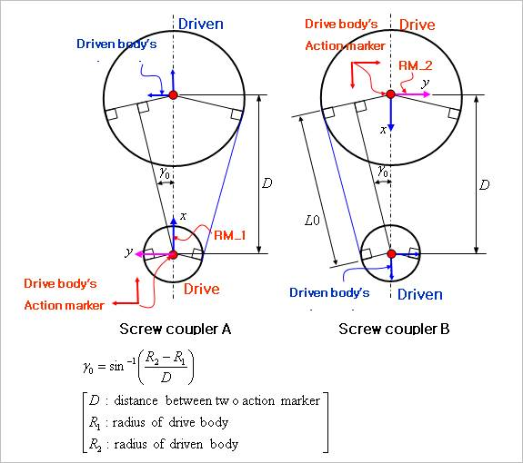
Figure 37.16 Chain Coupler simple diagrams
Drive body’s action marker is included a drive body.
Driven body’s action marker is included a driven body.
Base markers are included the mother body (Ground).
RMs are included the mother body (Ground).
Assembly method of chain coupler in case of more than 3 bodies, when you set the chain coupler for 3 bodies, three sets of screw coupler is attached. (It means that only one set of screw coupler is attached between two bodies.) There are two kinds of assembly method of chain coupler. (CW, CCW)
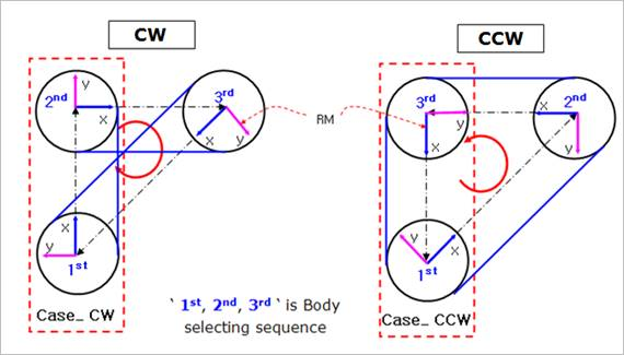
Figure 37.17 Assemble method of Chain Coupler