6.2.3.5. Parallel
A parallel joint constraints the z-axis of the marker of action body so that it remains parallel to the z-axis of the marker of the base body as shown in Figure 6.214. The action body is constrained relative to the base body. The marker of the action body can only rotate about one axis with respect to the coordinate system of the base body. This parallel joint has one rotational degree of freedom and three translational degrees of freedom.
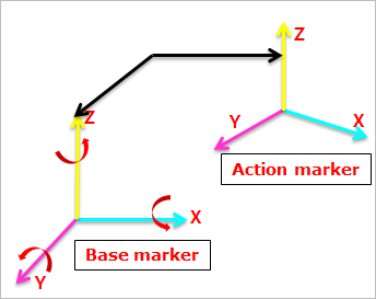
Figure 6.214 Definition of Parallel Joint
6.2.3.5.1. Modeling Options
The user can create a joint entity as follows.
Point, Point, Direction
Point: Selects a point on a base body.
Point: Selects a point on an action body.
Direction: Defines the z-axes of base and action markers.
Point, Point
Point: Selects a point on a base body.
Point: Selects a point on an action body.
Body, Body, Point, Point, Direction
Body: Selects a base body of the parallel joint.
Body: Selects an action body of the parallel joint.
Point: Selects a point on a base body.
Point: Selects a point on an action body.
Direction: Defines the z-axes of base and action markers.
Body, Body, Point, Point
Body: Selects a base body of the parallel joint.
Body: Selects an action body of the parallel joint.
Point: Selects a point on a base body.
Point: Selects a point on an action body.
6.2.3.5.2. Properties
The user can only define the force display using the Joint page.
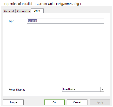
Figure 6.215 Parallel property page [Joint page]
Type: Shows the type of joint.
Force Display: Displays the resultant force vector graphically on Working Window.