30. Chain
Figure 30.1 Chain example
A chain is a reliable machine component, which transmits power by means of tensile forces, and is used primarily for power transmission and conveyance systems. Roller chain is a chain that has an inner plate, outer plate, pin, bushing, and roller. Silent chain has only plates and pins. Chain system can be modeled and analyzed in this toolkit. The toolkit consists of frequently used bodies and force elements, and chain links. Chain body system includes sprocket, roller(idler), guide rail and lateral guard. A chain link system has chain links and bushings. The chain links are connected by a single pin bushing. Contacts between chain links and the bodies such as sprocket, roller, guide rail and lateral guard can be defined, and contact compliance characteristics can be modified by a user. Chain links of a chain system are created by automatically duplicating a pair of chain link generated by a user. A pair of roller chain link consists of a roller link and pin link. An offset link is used when an odd number of chain links is required. A pair of silent chain link has an inner link and outer link. The chain links are connected by rubber bushings whose characteristics must be obtained prior to modeling a chain system.
About the coordinate system
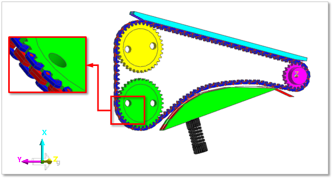
Figure 30.2 Coordinate system for the chain module
Chain system must be modeled in the coordinate system defined by the user. If a chain system has a different orientation, the whole system can be reoriented by using object control after creation.
Step to run Chain System
Model a chain body system such as sprocket, roller, guide rail and so on.
Create a pair of chain link.
Assemble the chain link system.
Define contact parameters and output.
Run the simulation.
- 30.1. Common UI
- 30.2. Geometric Entities
- 30.3. Segment Assembly
- 30.4. Specialized Outputs
- 30.5. Calculator
- 30.6. Connector
- 30.7. Specific Sensor