24.6. MTT2DAssembly
When the user enters the MTT2D subsystem, MTT2DAssembly appears under the MTT2Ds item in Database Window. The current rule is that an Assembly exists in one subsystem. Double-clicking on the MTT2DAssembly entity brings up a window where the user can define the current subsystem as a whole.
Figure 24.72 MTT2DAssembly entity in Database Window
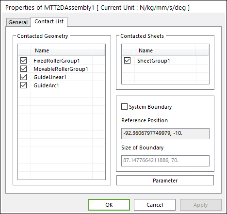
Figure 24.73 MTT2DAssembly property page
Contacted Geometry: All geometric entities that could contact Sheets are displayed. If the user does not check the box for a geometric entity, any contract between the geometry and the Sheets are ignored.
Contacted Sheets: All sheets that may contact Rollers and Guides are displayed.
System Boundary: Sheets only contact other geometric entities that lie within the defined system boundary, as shown in Figure 24.74. If the user does not check this option, RecurDyn automatically computes the system boundary for the user. The method for manually setting up the system boundary is explained in the following paragraphs.
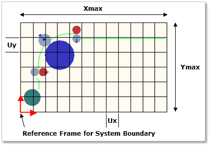
Figure 24.74 System boundary
Reference Position: The reference position defaults to the origin of the base (mother) body and is used to define the location of the bounding box. If the user checks on the button of the System Boundary, the user can edit the Reference Position.
Size of Boundary: The size of the bounding box is needed to efficiently search for possible contacts between bodies. The size is automatically computed, and the user can modify the values. If a Sheet contacts to other geometric entities out of the pre-defined range, the user must adjust the size values.
Parameter: This option lets the user set some contact parameters.
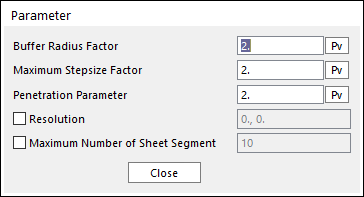
Figure 24.75 Parameter dialog box
Buffer Radius Factor: This factor sets the size of a geometric buffer around possible contacts. When a body enters the buffer zone, the integrator reduces the size of the time step so that the beginning of the contact is detected accurately. If the user increases the factor, the simulation time may increase. On the other hand, if the user decreases the factor, Sheet contacts may stop working. It is recommended to use the default value.
Maximum Stepsize Factor: If the user increases the factor, the maximum Stepsize of Solver decreases as explained above. In user’s model, if sheet contacts are not working and the speed of a sheet is fast, the user should increase the values of buffer radius factor and the maximum stepsize factor.
Penetration Parameter: This factor is used in definition of maximum penetration for a sheet and other geometry contact cases except sheet-roller contact. In the sheet-roller contact case, the maximum penetration is defined as radius of the roller.
Maximum penetration = Thickness of a sheet / 2.0 * Penetration parameter
If a calculated penetration is greater than the maximum penetration, the contact force is not generated.
Resolution: This is the size of each tile in the system boundary. As shown in Figure 24.74, the bounding box of a system is divided by several tiles. The values are automatically computed.
Maximum Number of Sheet Segment: This is the maximum number of sheet segment bodies that may be simultaneously contained in one tile.