6.4.3.14. Cylinder In Cylinder
A Cylinder In Cylinder Contact generates a force between two cylinders.
The cylinder and cylinder must belong to two different bodies.
The cylinder must be defined an action geometry and the cylinder must be defined a base geometry.
The action cylinder must be inside of the base cylinder initially.
The contact force can be generated with not only linear or exponential but also nonlinear spline characteristics to the contact penetration and its velocity.
6.4.3.14.1. Modeling Options
In the case of Cylinder In Cylinder contact, a cylinder geometry type is supported without base and action geometries when creating.
Cylinder, Cylinder
Cylinder: Selects a cylinder to define a base cylinder.
Cylinder: Selects a cylinder to define an action cylinder.
Cylinder, MultiCylinder
Cylinder: Selects a cylinder to define a base cylinder.
MultiCylinder: Selects some cylinders to define action cylinders.
Cylinder, Cylinder, Cylinder, Cylinder
Cylinder: Selects a cylinder to define a base cylinder.
Cylinder: Selects a cylinder to define an action cylinder.
Cylinder: Selects a cylinder to define another base cylinder.
Cylinder: Selects a cylinder to define another action cylinder.
MultiCylinder, MultiCylinder
MultiCylinder: Selects some cylinders to define base cylinders.
MultiCylinder: Selects some cylinders to define action cylinders.
MultiCylinder
MultiCylinder: Selects some cylinders to define base and action cylinders each other.
Note
In case of MultiCylinder modeling, contacts are created correctly if selecting the order of the radius of the cylinders.
6.4.3.14.2. Properties
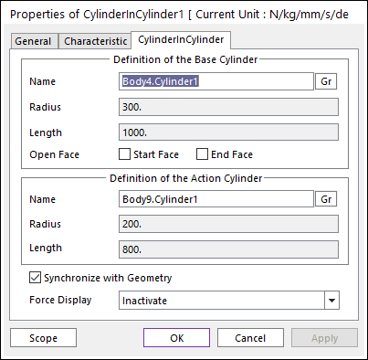
Figure 6.376 Properties of CylinderInCylinder dialog box
Definition of The Base Cylinder
Entity Name: Defines the name of base cylinder. The base cylinder can be dispatched from the Working Window by clicking Gr.
Radius: Shows the radius of base cylinder.
Length: Shows the length of base cylinder.
Open Face: The cylinder geometry has three faces. Two of the faces are in both end sides, and they are closed as default. If the user wants to open the side, the user can do it with using this option. The checked open faces are automatically shown on the Working Window.
Start Face is located in start point of the cylinder.
End Face is located in end point of the cylinder.
Definition of The Action Cylinder
Entity Name: Defines the name of action cylinder. The action cylinder can be dispatched from the Working Window by Gr.
Radius: Shows the radius of action cylinder.
Length: Shows the length of action cylinder.
Synchronize with Geometry
If this option is checked, Radius and Length in contact properties automatically defined with that of the specified graphics. (The default is checked.)
If the user unchecked this, the user can modify the contact properties.
Force Display: Graphically displays the resultant force vector on the view window.