30.2.8. Guide
A chain slack is eliminated by supporting the entire return side with a guide rail and installing a take-up on the driven shaft. The chain may vibrate considerably due to the characteristic frequency of the chain, impact period of the driven shaft, or the polygonal action of the chain and sprocket. Therefore, it is a very important to install a guide shoe to prevent vibration. The width and length of the contact surface of the guide must be large enough for the chain link to pass.
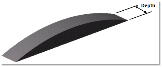
Figure 30.54 Guide rail
30.2.8.1. Modeling Options
The user can create a guide as follows.
MultiPoint
MultiPoint: Selects some points to define the guide.
30.2.8.2. Properties
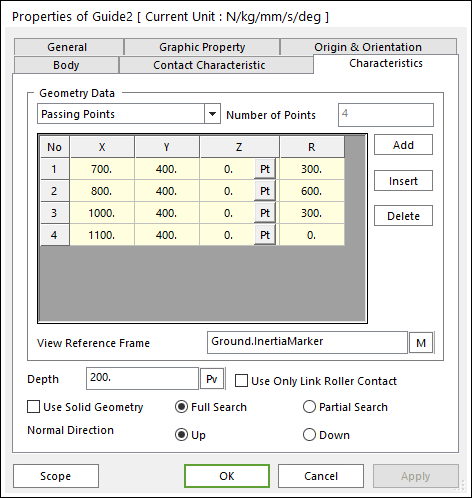
Figure 30.55 Guide property page [Characteristics page]
The Guide property page is shown in Figure 30.55. The parameters are explained below.
Geometry Data: There are 3 type methods to define a guide geometry. Those are Passing Points, Center Points and Radius, and Center Points and Arc Angle.
Passing Points
X, Y, Z: Defines a passing point of the guide based on View Reference Frame.
R: Defines a radius of the guide passing two points.
Center Points and Radius: Defines geometry data by using center points and radius.
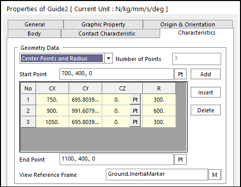
Figure 30.56 Guide property page [Characteristic page]
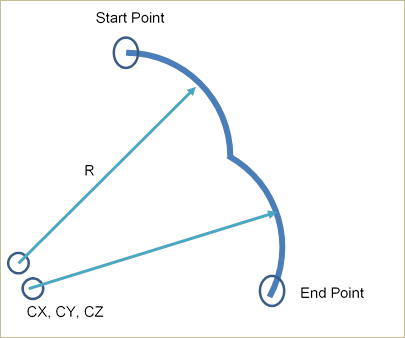
Figure 30.57 Definition for each data
Start Point: Defines a start point of the guide.
End Point: Defines an end point of the guide.
CX, CY, CZ: Defines a center point of the guide based on View Reference Frame.
R: Defines a radius of the guide with the center point.
Center Points and Arc Angle: Defines geometry data by using center points and arc angle.
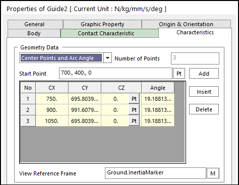
Figure 30.58 Guide property page [Characteristic page]
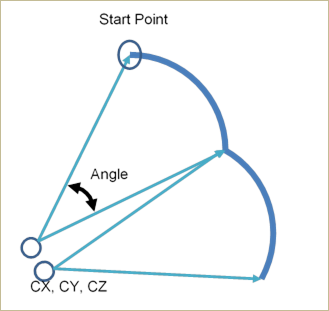
Figure 30.59 Definition for each data
Start Point: Defines a start point of guide.
CX, CY, CZ: Defines a center point of the guide based on View Reference Frame.
Angle: Defines a revolution angle of the guide.
Number of Points: Shows the number of points.
Add: Adds a row to the end of the table.
Insert: Inserts a row where the cursor is and move the current and later rows down.
Delete: Deletes the row where the cursor is and move the later rows up.
View Reference Frame: Defines a reference frame for points.
Depth: Defines the depth of guide.
Use Only Link Roller Contact: If the guide has narrower width than the pin length of a chain link, its function supports the contact between the Guide with the narrow width and the Roller Link of Roller and Multiplex.
Use Solid Geometry: The guide shape is shown from surface to solid.
Full Search: All links are searched for contact.
Partial Search: Some links are searched for contact in some boundary. It is used to reduce total solving time.
Normal Direction: Determines the contact direction.
30.2.8.2.1. Contact between a Guide and a Link
The guide rail is in contacts with the chain link in the two parts.
The surface of guide rail – the top/bottom surface of chain link plates
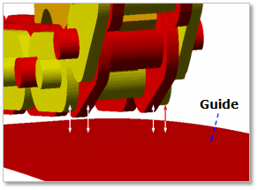
Figure 30.60 Contact between a guide and chain links
If the roller diameter of chain link is bigger than the height of roller link plate, the contact occurs as follows.
The surface of guide rail – the roller of chain link
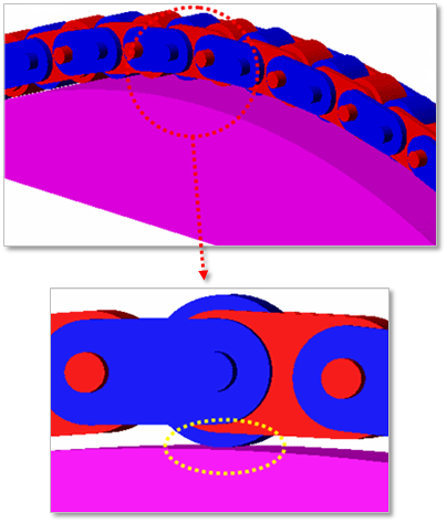
Figure 30.61 Contact between a guide and roller of chain links
If the guide width is narrower than the pin length of chain links, the contact happens when checking the option of Use Only Link Roller Contact.
The surface of the narrow guide rail – the roller link of chain links
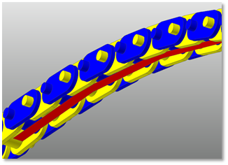
Figure 30.62 Contact between the narrow guide and chain links