31.3.1. 2D Contact
2D Contact generates a force between gear profiles. So, modified tooth geometry such as Crowning Effect is not considered.
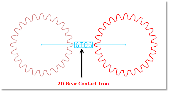
Figure 31.92 2D Gear Contact
Note
2D Contact with Bevel, Worm, Worm Gear are not supported.
31.3.1.1. Modeling Options
The user can define a 2D Contact as follows.
Body(Group), Body(Group)
Body(Group): Selects a base gear.
Body(Group): Selects an action gear.
31.3.1.2. Properties
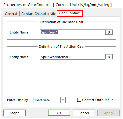
Figure 31.93 Gear Contact property page [Gear Contact page]
Definition of The Base Gear
Entity Name: Specifies the name of the base gear.
Definition of The Action Gear
Entity Name: Specifies the name of the action gear.
Force Display: Graphically displays the resultant force vector on the view window.
Contact Output File: When this function is checked, RecurDyn creates the contact output file for contact information between gears as follows. The name of output file is ‘ModelName_ContactName.out’.
Table 31.3 Contact Output File Format Col.
Variables
Descriptions
1
Time (sec)
Simulation Time
2
amount of contact point
Total number of calculated contact points
3
Pos_TX of gear_1 CM
Position X of base gear’s center marker
4
Pos_TY of gear_1 CM
Position Y of base gear’s center marker
5
Pos_TZ of gear_1 CM
Position Z of base gear’s center marker
6
Pos_PSI of gear_1 CM
Orientation Psi of base gear’s center marker
7
Pos_THETA of gear_1 CM
Orientation Theta of base gear’s center marker
8
Pos_PHI of gear_1 CM
Orientation Phi of base gear’s center marker
9
Pos_TX of gear_2 CM
Position X of action gear’s center marker
10
Pos_TY of gear_2 CM
Position Y of action gear’s center marker
11
Pos_TZ of gear_2 CM
Position Z of action gear’s center marker
12
Pos_PSI of gear_2 CM
Orientation Psi of action gear’s center marker
13
Pos_THETA of gear_2 CM
Orientation Theta of action gear’s center marker
14
Pos_PHI of gear_2 CM
Orientation Phi of action gear’s center marker
15
The index for contact points
16
Global contact position
Global contact position
17
Contact position based on gear_1
Contact position based on gear_1
18
Contact position base on gear_2
Contact position base on gear_2
19
Contact force based on gear_2
Contact force based on gear_2
20
Friction force based on gear_2
Friction force based on gear_2
31.3.1.2.1. Contact Characteristic
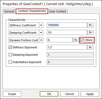
Figure 31.94 Gear Contact property page [Contact Characteristic page]
Contact Normal Force
The contact normal force is obtained by
where, k and c are the stiffness and damping coefficients which are determined by an experimental method, respectively. \(\delta\) and \({\dot{\delta }}\) are a penetration and time differentiation of the penetration, respectively. The exponents \({{m}_{1}}\) and \({{m}_{2}}\) generates a non-linear contact force and the exponent \({{m}_{3}}\) yields an indentation damping effect.
Characteristic: Defines the contact properties such as the stiffness coefficient, damping coefficient, and friction coefficients. Also, these coefficients can be given as user-defined spline curves.
Stiffness Coefficient: Specifies a stiffness coefficient for the contact normal force.
Stiffness Spline: The spline shows the contact normal force for the penetration. For more information, click here.
Damping Coefficient: Specifies a damping coefficient for the contact normal force.
Damping Spline: The spline shows the contact normal force for the velocity of penetration. For more information, click here.
Dynamic Friction Coefficient: Specifies a dynamic friction coefficient for the contact friction force. It has three options.
Dynamic Friction Coefficient: The constant friction coefficient is applied.
Friction Force Spline: The spline shows the fiction force for the relative velocity. It is recommended to use the spline that x and y values are defined as positive.
Friction Coefficient Spline: The spline shows the friction coefficient for the relative velocity.
More: Specifies some friction coefficients for the contact friction force.
Stiffness and Damping Exponent: Generates a non-linear contact normal force.
Indentation Exponent: Yields an indentation damping effect. When the penetration is very small, the contact force may be negative due to a negative damping force, which is not realistic. This situation can be overcome by using the indentation exponent greater than one.
Friction Force
Friction Coefficient: Specifies the dynamic friction coefficient for the contact friction force.
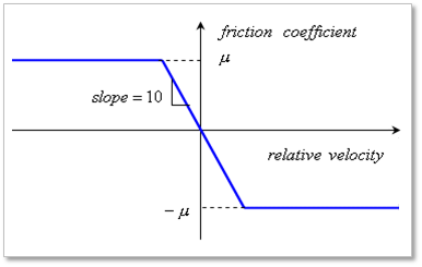
Figure 31.95 Relationship between relative velocity and friction coefficient
More: Specifies some friction coefficients for the contact friction force as shown in Figure 31.96.
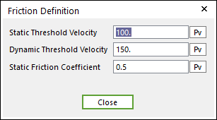
Figure 31.96 Friction Definition dialog box
Static Threshold Velocity: If the relative velocity between a contact pair is less than this value, the friction coefficient is defined as following.
\(\mu =\text{step5}(\nu ,\,\,-{{\nu }_{s}},\,\,{{\mu }_{s}},\,\,{{\nu }_{s}},\,\,-{{\mu }_{s}}\,)\)
Dynamic Threshold Velocity: If the relative velocity between a contact pair is greater than:
This value, the friction coefficient is the same as the specified dynamic friction coefficient.
Static Threshold Velocity and less than this value, the friction coefficient is defined as following.
\(\mu =\text{step5}\,(\nu ,\,\,{{\nu }_{s}},\,\,-{{\mu }_{s}},\,\,{{\nu }_{d}},\,\,-{{\mu }_{d}}\,)\)
Static Friction Coefficient: Specifies a static friction coefficient.
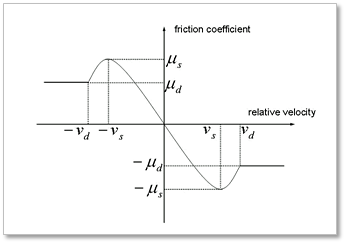
Figure 31.97 Relationship between relative velocity and friction coefficient
The friction force of contact elements is determined by the following equations.
\({{f}_{f}}=-\,\text{sign}\,(v)\,\,\left| \mu (v) \right|\,\,\left| {{f}_{n}} \right|\)
The friction force of contact element