6.6.2. Laser Sensor
A Laser Sensor finds out whether the z direction of a laser marker passes target geometry or not. When the laser meets the target geometry, a distance from the starting point to the target geometry is measured. A rigid body, RFlex body and a FFlex body are available as the target geometry.
Product |
Geometry |
Professional |
Solid, Single surface, Multi surface |
FFlex |
Single patchset, Multi patchset |
RFlex |
Single patchset, Multi patchset |
MTT3D |
Single patchset, Multi patchset |
Belt |
Single patchset, Multi patchset |
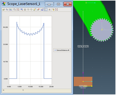
Figure 6.416 Laser Sensor
6.6.2.1. Modeling Options
The user can create a sensor by the following procedure.
Point, Point, Surface(PatchSet)
Point: Selects a point on a base body to define a location of laser sensor.
Point: Inputs a point. A distance and a direction of laser sensor are defined as the difference of first point and second point.
Surface: Selects a surface or a patch set of FFlexBody to define a target body.
Point, Point, Solid(PatchSet)
Point: Selects a point on a base body to define a location of laser sensor.
Point: Inputs a point. A distance and a direction of laser sensor are defined as the difference of first point and second point.
Solid(PatchSet): Selects a solid or a patch set of FFlexBody to define a target body.
Point, Point, MultiSurface(PatchSet)
Point: Selects a point on a base body to define a location of laser sensor.
Point: Inputs a point. A distance and a direction of laser sensor are defined as the difference of first point and second point.
MultiSurface(PatchSet): Selects some surfaces or patch sets of FFlexBody to define a target body.
Point, Point, MultiSolid(PatchSet)
Point: Selects a point on a base body to define a location of laser sensor.
Point: Inputs a point. A distance to limit the range of laser sensor and a direction of laser sensor are defined as the difference of first point and second point.
MultiSolid(PatchSet): Selects some solids or patch sets of FFlexBody to define a target body.
Point, Direction, Distance, Surface(PatchSet)
Point: Selects a point on a base body to define a location of laser sensor.
Direction: Defines a direction of z-axis of laser sensor.
Distance: Inputs a distance to limit the range of laser sensor.
Surface(PatchSet): Selects a surface or a patch set of FFlexBody to define a target body.
Point, Direction, Distance, Solid(PatchSet)
Point: Selects a point on a base body to define a location of laser sensor.
Direction: Defines a direction of z-axis of laser sensor.
Distance: Inputs a distance to limit the range of laser sensor.
Solid(PatchSet): Selects a solid or a patch set of FFlexBody to define a target body.
Point, Direction, Distance, MultiSurface(PatchSet)
Point: Selects a point on a base body to define a location of laser sensor.
Direction: Defines a direction of z-axis of laser sensor.
Distance: Inputs a distance to limit the range of laser sensor.
MultiSurface(PatchSet): Selects some surfaces or patch sets of FFlexBody to define a target body.
Point, Direction, Distance, MultiSolid(PatchSet)
Point: Selects a point on a base body to define a location of laser sensor.
Direction: Defines a direction of z-axis of laser sensor.
Distance: Inputs a distance to limit the range of laser sensor.
MultiSolid(PatchSet): Selects some solids or patch sets of FFlexBody to define a target body.
Body, Point, Direction, Distance, Surface(PatchSet)
Body: Selects a body to define the parent body of laser sensor.
Point: Selects a point on a base body to define a location of laser sensor.
Direction: Defines a direction of z-axis of laser sensor.
Distance: Inputs a distance to limit the range of laser sensor.
Surface(PatchSet): Selects a surface or a patch set of FFlexBody to define a target body.
Body, Point, Direction, Distance, Solid(PatchSet)
Body: Selects a body to define the parent body of laser sensor.
Point: Selects a point on a base body to define a location of laser sensor.
Direction: Defines a direction of z-axis of laser sensor.
Distance: Inputs a distance to limit the range of laser sensor.
Solid(PatchSet): Selects a solid or a patch set of FFlexBody to define a target body.
Body, Point, Direction, Distance, MultiSurface(PatchSet)
Body: Selects a body to define the parent body of laser sensor.
Point: Selects a point on a base body to define a location of laser sensor.
Direction: Defines a direction of z-axis of laser sensor.
Distance: Inputs a distance to limit the range of laser sensor.
MultiSurface (PatchSet): Selects some surfaces or patch sets of FFlexBody to define a target body.
Body, Point, Direction, Distance, MultiSolid(PatchSet)
Body: Selects a body to define the parent body of laser sensor.
Point: Selects a point on a base body to define a location of laser sensor.
Direction: Defines a direction of z-axis of laser sensor.
Distance: Inputs a distance to limit the range of laser sensor.
MultiSolid (PatchSet): Selects some solids or patch sets of FFlexBody to define a target body.
6.6.2.2. Properties
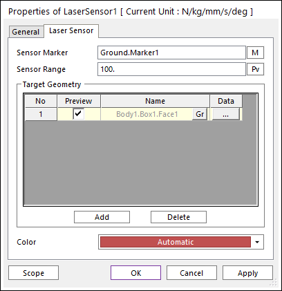
Figure 6.417 Laser Sensor property page
Sensor Marker: Defines a sensor marker. The sensor marker’s position and the Z direction is used as the starting point and the direction of laser.
Sensor Range: Defines the maximum range of laser. If the target geometry is met over the range, the result is neglected.
Target Geometry: Defines the target of laser. When laser meets the target at first, the length from the laser to meeting position is returned as a result.
Gr: choose a different Target Geometry.
Data
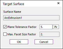
Figure 6.418 Target Surface dialog box
Plane Tolerance Factor: Specifies the surface tolerance factor as a value from 0 to 10. A smaller value produces a more refined patch. For more information, click here.
Max. Facet Size Factor: Specifies the max. facet size factor as a value from 0.01 to 10. This value controls the maximum size of triangular or quadrilateral patch length. Even though box geometry, if this value is defined (checked), box geometry can be used with lots of triangular or quadrilateral patches as shown in the below figure.
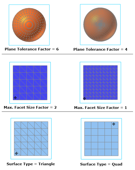
Figure 6.419 Example of Plane Tolerance Factor, Max. Facet Size Factor and Quad Surface Type
Add: Adds some of the target geometry.
Delete: Deletes some of the target geometry.
Color: Defines the color of sensor icon.