39.2.2.4. Piston Section Setting
Here, user can set all options related to piston body.
Profile
Profile defines an offset data in angle and height coordinate. User can apply arbitrary piston shape to EHD analysis by setting this offset table data. In the case of piston profile, RecurDyn supports two profiles which are superimposed in the EHD analysis.
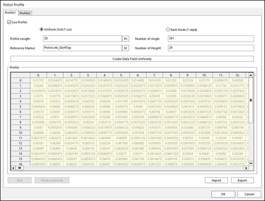
Figure 39.48 Uniform Grid type in Piston Profile dialog box
Use Profile: On/Off check option.
Uniform Grid (*.csv): Define profile using uniform coordinate in 2D table.
Profile Length (L): Defines profile height length.
Number of Angle: Defines number of angles of profile data in angle direction.
Number of Height: Defines number of heights of profile data in height direction.
Reference Marker: Select reference marker to define profile data. Height direction of profile is the same as Y axis of the marker and angle direction is the same as rotation direction from X to –Z axis.
Create Data Field Uniformly: Make profile data according to defined height length (L), number of angle and number of heights automatically. Profile coordinate in height direction is generated at interval where profile length is divided by the (number of height - 1). The height range is from –L/2 to L/2. Profile coordinate in angle direction is generated at interval where 360 degrees are divided by the number of angles. Default value for offset is ‘0’
Plot: Display curve plot for the profile data. User can click angle or height coordinate. And then, if the user clicks Plot, curve plot for profile is displayed like below figure.
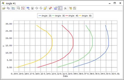
Figure 39.49 Curve plot for profile data
Plot (Combined): Display combined curve plot for profile1 and profile2. User can click angle or height coordinate. And then, if the user clicks Plot (Combined), combined curve plot for two profiles is displayed like below figure.
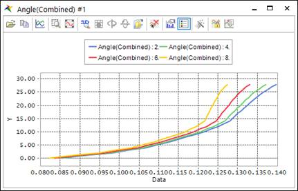
Figure 39.50 Combined Curve plot for two profile data
Import & Export: User can make profile data chart of *.csv file format by exporting profile chart in dialog. Additionally, user can also import the *.csv file and modify current profile data in dialog. Below figure is the example of *.csv file format for profile information. Profile data can be modified in the only *.csv file.
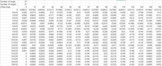
Figure 39.51 Profile data in *.csv file format
Each Node (*.repd): Define profile using non uniform profile data in which node position and corresponding profile value are included.
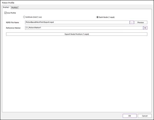
Figure 39.52 Each Node type in Piston Profile dialog box
REPD File Name: Defines *.repd file path having the non-uniform profile data where patch node position and corresponding profile value is included. *repd file consists of csv format. Thus user can edit the contents of it by changing the extension from *.repd to *.csv. After editing the contents of it, user have to change the extension of it to *.repd in order to load this file in the profile function. *repd file structure is as follows:
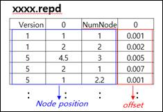
Figure 39.53 File structure of *.repd file
Preview: User can check profile information is applied correctly by contour image.
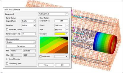
Figure 39.54 Preview contour for applied profile to the patch nodes
Reference Marker: Defines reference marker in order to define node position in the *.repd file.
Export Node Position(*.repd): Make *.repd file which includes node position for the selected patch and profile value having all zero for corresponding nodes.
Output Point for Clearance
It defines points on action patch set in angle and height coordinate with respect to reference marker. Clearance for these points can be output in RecurDyn plot file.
The below figure shows the step for Output Point for Clearance. First, set the reference marker on the action body and specify the height and angle values to be exported. Then, user can confirm the clearance result at those points in RPLT plot.
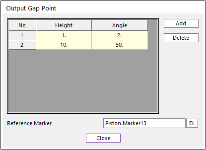
Figure 39.55 Output Gap Point dialog box
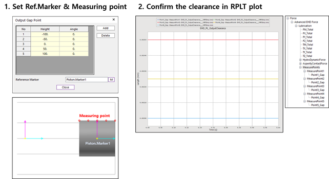
Figure 39.56 Step for Output Point for Clearance