5.10.5. Animation Scaling
In generally, the system component has a different scale magnitude for a displacement. For example, each component of total assembled car moving the straight road of 10m has a small relative displacement. The displacement of suspension component relative to the attached tire is very small rather than the global motion. Sometimes, it becomes one of the main reasons of simulation that observing such a small displacement. But this observation is not easy to capture. So, RecurDyn supports the Animation Scaling function to enlarge the relatively small displacement. The below figure shows a concept of scaling.
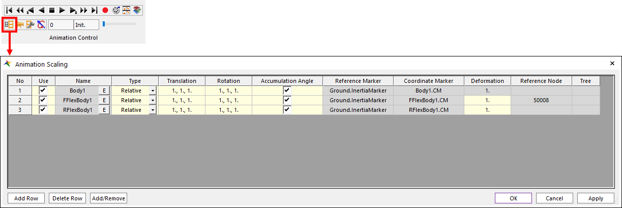
Figure 5.92 Animation Scaling dialog box
The user can use a way to set and modify the Animation Scaling option. To activate the Animation Scaling function, the user must add target bodies on the Animation Scaling dialog.
Animation Scaling options
Use checkbox: Enables the animation scaling
Name: Body name. The user can select using the “E” button.
Type: There are two types, Relative and Absolute. Default is Relative type.
Translation: Translation scaling factors is a 3x1 vector. The reference frame of the vector is set to the inboard joint marker for the Relative type. In the case of the Absolute type, the reference frame of the vector is set to the Reference Marker.
Rotation: Rotation scaling factors is a 3x1 vector. The reference frame of the vector is set to the inboard joint marker for the Relative type. In the case of the Absolute type, the reference frame of the vector is set to the Reference Marker.
Accumulation Angle checkbox: It is an angle measure option for rotation animation scaling. In order to measure angles, the arctangent function is used. Therefore, discontinuous animation can appear every nearest 180.0 degree difference when Accumulation Angle option is not used. If the checkbox is checked, then the accumulated angle measure method is used. When a body rotates a range from \(-{\theta}_1\) to \(\theta_2\) with simulation time growing, in this case, the Accumulation Angle option is not recommended.
Reference Marker: If the Absolute type is used, then this option is enabled.
Coordinate Marker: If the Absolute type is selected, then the user can select the coordinate marker which is a basis of the rigid body motion of the Absolute scaling type.
Deformation: Deformation scaling factor. If the body is a flexible body(FFlex or RFlex), then this deformation factor is enabled.
Reference Node: If the Absolute type and the FFlex body are selected, then the user can set a reference node whose position and orientation are defined as a generalized coordinate for the rigid motion.
Tree: Shows a partial connection body list of the spanning tree for the Relative type. The body list is always the previous connection of the selected body. It also shows the message window, whenever the left mouse clicks.
Add button: Adding a target body to enlarge animation.
Delete button: Delete the select body in the list.
Relative Animation Scaling algorithm
The spanning tree is needed for the Relative Animation Scaling. Because the reference and coordinate of each body are automatically defined as the Joint marker. If there is a closed-loop condition for a joint in the spanning tree, then the joint is defined as a cut-joint. The cut-joint is not calculated in the Relative Animation Scaling. The calculation order starts from the Ground body to the end node of the spanning tree. Regarding a floating body(= there’s no joint connection) and a sub-set of joint tree (= the joint tree isn’t connected to the ground), Relative Animation Scaling automatically defines and handles a virtual joint between the floating body and the Ground body.
The coordinate is set to the inboard joint marker position and orientation. The inboard joint means the nearest joint to the ground body in the spanning tree.
In the case of flexible bodies, first the reference node which is a reference of the joint marker configuration is updated. After the Joint node updating, the orther nodes are updated.
When a body has a fixed joint in the spanning tree, then the body is not changed any relative translation and rotation scaling factors. Because, the relative motion isn’t in the fixed joint.
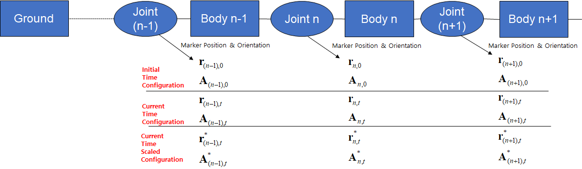
Figure 5.93 Coordinate definitions of Relative Translation/Rotation Scaling
The following translation and rotation scalings are calculated.
Relative Rotation Scaling: \({\bf{A}_{n,t}^{*}}={\bf{A}_{(n-1),t}^{*}}{\bf{A}_{(n-1)n,0}}{\bf{A}_{(n-1)n,0t}^{*}}\)
- where,
- \({\bf{A}_{(n-1)n,0t}^{*}} \equiv {{f}_{angle}^{-1}}([{s_r}_x {\theta}_x, {s_r}_y {\theta}_y, {s_r}_z {\theta}_z]^T)\)\([{\theta}_x, {\theta}_y, {\theta}_z]^T \equiv {{f}_{angle}}({{\bf{A}}_{(n-1)n,0}^{T}}{\bf{A}_{(n-1)n,t}})\)\({\bf{A}_{(n-1)n,t}} \equiv {\bf{A}_{(n-1),t}^{T}} {\bf{A}_{n,t}}\)\({\bf{A}_{(n-1)n,0}} \equiv {\bf{A}_{(n-1),0}^{T}}{\bf{A}_{n,0}}\)\({f}_{angle}()\) : A function for angle measure\({\bf{s_r}} = [{s_r}_x, {s_r}_y, {s_r}_z]^T\) : Rotation Scaling Factor\({\bf{A}_{(n-1),t}^{*}}\) : The scaled orientation matrix of the (n-1) body
Relative Translation Scaling: \({\bf{r}_{n,t}^{*}}= {\bf{r}_{(n-1),t}^{*}}+{\bf{A}_{(n-1),t}^{*}}{\bf{d'}_{(n-1)n,0}}+{\bf{A}_{(n-1),t}^{*}}([{s_t}_x d_x, {s_t}_y d_y, {s_t}_z d_z]^T)\)
- where,
- \([d_x, d_y, d_z]^T \equiv ({\bf{d'}_{(n-1)n,t}}-{\bf{d'}_{(n-1)n,0}})\)\({\bf{d'}_{(n-1)n,t}} \equiv {\bf{A}_{(n-1),t}^{T}}({\bf{r}_{n,t}}-{\bf{r}_{(n-1),t}})\)\({\bf{d'}_{(n-1)n,0}} \equiv {\bf{A}_{(n-1),0}^{T}}({\bf{r}_{n,0}}-{\bf{r}_{(n-1),0}})\)\({\bf{s_t}} = [{s_t}_x, {s_t}_y, {s_t}_z]^T\) : Translation Scaling Factor\({\bf{A}_{(n-1),t}^{*}}\) : The scaled position vector of the (n-1) body
Absolute Animation Scaling algorithm
The user can changes the reference which default is set to Ground.InertiaMarker. The coordinates of Rigid body is a geometry reference frame. The coordinates of FFlex body is one of (First joint marker, BC first Node, first node, or user’s selected node). The coordinates of RFlex body is the RFlex Body Reference Frame. The following equations are calculated.
Absolute Rotation Scaling: \({\bf{A}_{i,t}^{*}}={\bf{A}_{r,t}}{\bf{A}_{ri,0}}{\bf{A}_{ri,0t}^{*}}\)
- where,
- \({\bf{A}_{ri,0t}^{*}} \equiv {{f}_{angle}^{-1}}([{s_r}_x {\theta}_x, {s_r}_y {\theta}_y, {s_r}_z {\theta}_z]^T)\)\([{\theta_x}, {\theta_y}, {\theta_z}]^T \equiv {{f}_{angle}}({\bf{A}_{ri,0}^{T}}{\bf{A}_{ri,t}})\)\({\bf{A}_{ri,t}} \equiv {\bf{A}_{r,t}^{T}}{\bf{A}_{i,t}}\)\({\bf{A}_{ri,0}} \equiv {\bf{A}_{r,0}^{T}}{\bf{A}_{i,0}}\)\({\bf{A}_{r,t}}\) and \({\bf{A}_{r,0}}\) : The orientation matrices of the Reference Marker\({\bf{A}_{i,t}}\) and \({\bf{A}_{i,0}}\) : The orientation matrices of an arbitrary body \(i\)\({\bf{s_r}} = [ {s_r}_x, {s_r}_y, {s_r}_z ]^T\): Rotation Scaling Factor
Absolute Translation Scaling: \({\bf{r}_{i,t}^{*}}={\bf{r}_{r,t}}+{\bf{A}_{r,t}}{\bf{d'}_{ri,0}}+{\bf{A}_{r,t}} ([{s_t}_x d_x, {s_t}_y d_y, {s_t}_z d_z]^T)\)
- where,
- \([d_x, d_y, d_z]^T \equiv ({\bf{d'}_{ri,t}}-{\bf{d'}_{ri,0}})\)\({\bf{d'}_{ri,t}} \equiv {\bf{A}_{r,t}^{T}}({\bf{r}_{i,t}}-{\bf{r}_{r,t}})\)\({\bf{d'}_{ri,0}} \equiv {\bf{A}_{r,0}^{T}}({\bf{r}_{i,0}}-{\bf{r}_{r,0}})\)\({\bf{r}_{r,t}}\) and \({\bf{r}_{r,0}}\) : The position vectors of the Reference Marker\({\bf{A}_{i,t}}\) and \({\bf{A}_{i,0}}\) : The position vectors of an arbitrary body \(i\)\({\bf{s_t}} = [{s_t}_x, {s_t}_y, {s_t}_z]^T\): Translation Scaling Factor
Table 5.16 Comparison to the both types Relative type
Absolute type
Pre-calculation & Calculation Order
Spanning Tree
There’s no requirement
Coordinates of Rigid
Inboard Joint Marker
Coordinate Marker
Coordinates of FFlex
Inboard Joint Marker
Coordinate Marker (Parent node of the coordinate marker is set to the Reference Node.)
Coordinates of RFlex
Inboard Joint Marker
Coordinate Marker
Scaling Target
Relative joint motion in the spanning tree
Displacement between reference marker and Coordinate Marker of the target body
Deformation Scaling algorithm
Deformation scaling of the RFlex Body: The modal coordinates are scaled.
Deformation scaling of the FFlex Body
Rotation scaling target: \({\bf{A}}_{rp,t}^{*} \equiv {({\bf{A}}_{r,0}^T{\bf{A}}_{p,0})f_{angle}}^{-1}(s_d {f_{angle}}(({\bf{A}}_{r,0}^T{\bf{A}}_{p,0})^T({\bf{A}}_{r,t}^T{\bf{A}}_{p,t})))\)
Translation scaling target: \(s_d({\bf{d'}}_{rp,t}-{\bf{d'}}_{rp,0})\)
- where,
- \({\bf{A}}_{r,t}\) and \({\bf{A}}_{r,0}\) : The orientation matrices of the reference node with simulation time and initial time(=0.0sec).\({\bf{r}}_{r,t}\) and \({\bf{r}}_{r,0}\) : The position vectors of the reference node with simulation time and initial time(=0.0sec).\({\bf{A}}_{p,t}\) and \({\bf{A}}_{p,0}\) : The orientation matrices of an arbitrary node \(p\) with simulation time and initial time(=0.0sec).\({\bf{r}}_{p,t}\) and \({\bf{r}}_{p,0}\) : The position vectors of an arbitrary node \(p\) with simulation time and initial time(=0.0sec).\(s_d\): Deformation scaling factor\(\bf{d'}_{rp,0} \equiv {\bf{A}_{r,0}^{T}}({\bf{r}_{p,0}}-{\bf{r}_{r,0}})\)\(\bf{d'}_{rp,t} \equiv {\bf{A}_{r,t}^{T}}({\bf{r}_{p,t}}-{\bf{r}_{r,t}})\)
Updated \(p\) node orientation matrix: \({\bf{A}}_{p,t}^{*} = {\bf{A}}_{r,t}^{*}{\bf{A}}_{rp,t}^{*}\)
Updated \(p\) node position: \({\bf{r}_{p,t}^{*}} = {\bf{r}_{r,t}^{*}} + {\bf{A}_{r,t}^{*}} {\bf{d'}_{rp,0}} + s_d{\bf{A}_{r,t}^{*}} ({\bf{d'}}_{rp,t} - {\bf{d'}}_{rp,0})\)
where, \({\bf{A}}_{r,t}^*\) and \({\bf{r}}_{r,t}^*\) : The orientation matrix and position vector of the reference node updated by the Relative (or the Absolute) type.