10.1.8. Stress Analysis
RecurDyn/RFlex uses the stress shape and modal coordinate to recover the stress time history. RecurDyn/RFlex provides two different methods to calculate the stress shape matrix. One method is to use the displacement mode shape matrix to generate the strain shape matrix and the other method is to import the stress shape matrix directly from FE Softwares.
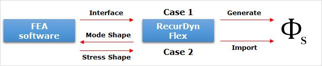
Figure 10.7 Concept of Stress recovery
Stress and strain recovery using stress and strain shape matrix does not support for the beam type elements. But, following beam elements can be shown the stress and strain results. The stress and strain recovery are used the FFlex Beam stress and strain recovery function. To calculate stress and strain, all Beam related information is written in the RFI file.
Beam Stress and Strain recovery (using the FFlex Beam function) |
|
|---|---|
Ansys |
Beam188, Beam189 |
MSC Nastran |
CBEAM, CBAR |
I-DEAS |
Linear Beam, Tapered Beam, Curved Beam |
10.1.8.1. Strain Shapes matrix
A strain shape is generated by the selected mode shapes.
The strain (\(\boldsymbol{\varepsilon}^{'}\)) are evaluated by superposition of strain shapes (\(\boldsymbol{\Phi}_{\varepsilon }^{{}}\)) which scaled by the modal coordinates (\(\mathbf{a}\)).
\(\boldsymbol{\varepsilon}^{'}=\sum\limits_{i}{\boldsymbol{\Phi}_{\varepsilon }^{i}}\cdot\mathbf{a}_i\)
The strain of a node is calculated as follows.
\(\left[ \begin{matrix} {{{{\varepsilon}'}}_{x}} \\ {{{{\varepsilon }'}}_{y}} \\ {{{{\varepsilon }'}}_{z}} \\ {{{{\gamma }'}}_{xy}} \\ {{{{\gamma }'}}_{yz}} \\ {{{{\gamma }'}}_{zx}} \\ \end{matrix} \right]=\left[ \begin{matrix} \varepsilon _{x}^{1} & \cdots & \varepsilon _{x}^{i} & \cdots \\ \varepsilon _{y}^{1} & \cdots & \varepsilon _{y}^{i} & \cdots \\ \varepsilon _{z}^{1} & \cdots & \varepsilon _{z}^{i} & \cdots \\ \gamma _{xy}^{1} & \cdots & \gamma _{xy}^{i} & \cdots \\ \gamma _{yz}^{1} & \cdots & \gamma _{yz}^{i} & \cdots \\ \gamma _{zx}^{1} & \cdots & \gamma _{zx}^{i} & \cdots \\ \end{matrix} \right]\left[ \begin{matrix} {{a}_{1}} \\ \vdots \\ {{a}_{i}} \\ \vdots \\ \end{matrix} \right]\)
The reference frame of the above strain tensor is RFlex body reference frame. Therefore, the strain with respect to Global.Inertia reference frame is computed as below tensor transformation.
\(\boldsymbol{\varepsilon} =\mathbf{A}\boldsymbol{\varepsilon}'{{\mathbf{A}}^{T}}\)
Where,
\(\mathbf{A}\) is an orientation matrix of RFlex body reference frame.
\(\boldsymbol{\varepsilon}'=\left[ \begin{matrix} {{{{\varepsilon }'}}_{x}} & \tfrac{1}{2}{{{{\gamma }'}}_{xy}} & \tfrac{1}{2}{{{{\gamma }'}}_{zx}} \\ \tfrac{1}{2}{{{{\gamma }'}}_{xy}} & {{{{\varepsilon }'}}_{y}} & \tfrac{1}{2}{{{{\gamma }'}}_{yz}} \\ \tfrac{1}{2}{{{{\gamma }'}}_{zx}} & \tfrac{1}{2}{{{{\gamma }'}}_{yz}} & {{{{\varepsilon }'}}_{z}} \\ \end{matrix} \right]\).
\({{\varepsilon }_{mises}}={{\left( \cfrac{2}{9}\left[ {{\left( {{\varepsilon }_{1}}-{{\varepsilon }_{2}} \right)}^{2}}+{{\left( {{\varepsilon }_{2}}-{{\varepsilon }_{3}} \right)}^{2}}+{{\left( {{\varepsilon }_{3}}-{{\varepsilon }_{1}} \right)}^{2}} \right] \right)}^{\cfrac{1}{2}}}\)
10.1.8.2. Stress Shapes matrix
A stress shape is generated by the strain shapes and elasticity matrix. The stress \(\boldsymbol{\sigma}'\) are evaluated by superposition of stress shapes \({\boldsymbol{\Phi}_{\sigma}}\) which scaled by the modal coordinates \(\mathbf{a}\).
\(\boldsymbol{\sigma}'=\sum\limits_{i}\boldsymbol{\Phi}_{\sigma}^{i}\cdot\mathbf{a}_i\)
The stress of a node is calculated as follows.
\(\left[ \begin{matrix} {{{{\sigma }'}}_{x}} \\ {{{{\sigma }'}}_{y}} \\ {{{{\sigma }'}}_{z}} \\ {{{{\sigma }'}}_{xy}} \\ {{{{\sigma }'}}_{yz}} \\ {{{{\sigma }'}}_{zx}} \\ \end{matrix} \right]=\left[ \begin{matrix} \sigma _{x}^{1} & \cdots & \sigma _{x}^{i} & \cdots \\ \sigma _{y}^{1} & \cdots & \sigma _{y}^{i} & \cdots \\ \sigma _{z}^{1} & \cdots & \sigma _{z}^{i} & \cdots \\ \sigma _{xy}^{1} & \cdots & \sigma _{xy}^{i} & \cdots \\ \sigma _{yz}^{1} & \cdots & \sigma _{yz}^{i} & \cdots \\ \sigma _{zx}^{1} & \cdots & \sigma _{zx}^{i} & \cdots \\ \end{matrix} \right]\left[ \begin{matrix} {{a}_{1}} \\ \vdots \\ {{a}_{i}} \\ \vdots \\ \end{matrix} \right]\)
The reference frame of the above strain tensor is RFlex body reference frame. Therefore, the strain with respect to Global.Inertia reference frame is computed as below tensor transformation.
\(\mathbf{\sigma }=\mathbf{A}\boldsymbol{\sigma}'\mathbf{A}^{T}\)
Where, \(\mathbf{A}\) is an orientation matrix of RFlex body reference frame.
\({{\sigma }_{mises}}={{\left( \cfrac{1}{2}\left[ {{\left( {{\sigma }_{1}}-{{\sigma }_{2}} \right)}^{2}}+{{\left( {{\sigma }_{2}}-{{\sigma }_{3}} \right)}^{2}}+{{\left( {{\sigma }_{3}}-{{\sigma }_{1}} \right)}^{2}} \right] \right)}^{\,\frac{1}{2}}}\)