6.3.3.2. Beam
A beam force is defined on the positive x-axis of a base marker, as shown in Figure 6.267.
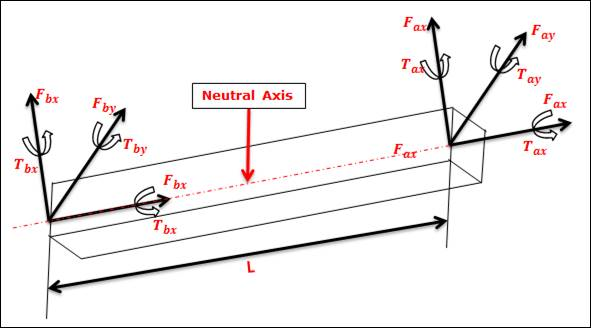
Figure 6.267 Base and action markers for the Beam Force
6.3.3.2.1. Modeling Options
The user can create a force entity as follows.
Point, Point
Point: Selects a point on a base body. This point defines a location on which the reaction force is applied.
Point: Selects a point on an action body. This point defines a location on which the action force is applied.
Body, Body, Point, Point
Body: Selects a base body of beam force.
Body: Selects an action body of beam force.
Point: Selects a point on a base body. This point defines a location on which the reaction force is applied.
Point: Selects a point on an action body. This point defines a location on which the action force is applied.
6.3.3.2.2. Properties
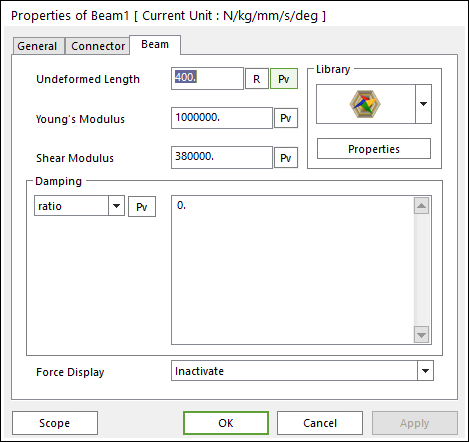
Figure 6.268 Beam property page
The forces and torques are defined by Timoshenko beam theory [7] and are applied to the action marker as follows:
\(\begin{aligned} & \left[ \begin{matrix} {{F}_{ax}} \\ {{F}_{ay}} \\ {{F}_{az}} \\ {{T}_{ax}} \\ {{T}_{ay}} \\ {{T}_{az}} \\ \end{matrix} \right]=-\left[ \begin{matrix} {{K}_{11}} & 0 & 0 & 0 & 0 & 0 \\ 0 & {{K}_{22}} & 0 & 0 & 0 & {{K}_{26}} \\ 0 & 0 & {{K}_{33}} & 0 & {{K}_{35}} & 0 \\ 0 & 0 & 0 & {{K}_{44}} & 0 & 0 \\ 0 & 0 & {{K}_{35}} & 0 & {{K}_{55}} & 0 \\ 0 & {{K}_{26}} & 0 & 0 & 0 & {{K}_{66}} \\ \end{matrix} \right]\left[ \begin{matrix} x-L \\ y \\ z \\ {{\theta }_{ab1}} \\ {{\theta }_{ab2}} \\ {{\theta }_{ab3}} \\ \end{matrix} \right]-\left[ \begin{matrix} {{C}_{11}} & {{C}_{12}} & {{C}_{13}} & {{C}_{14}} & {{C}_{15}} & {{C}_{16}} \\ {{C}_{21}} & {{C}_{22}} & {{C}_{23}} & {{C}_{24}} & {{C}_{25}} & {{C}_{26}} \\ {{C}_{31}} & {{C}_{32}} & {{C}_{33}} & {{C}_{34}} & {{C}_{35}} & {{C}_{36}} \\ {{C}_{41}} & {{C}_{42}} & {{C}_{43}} & {{C}_{44}} & {{C}_{45}} & {{C}_{46}} \\ {{C}_{51}} & {{C}_{52}} & {{C}_{53}} & {{C}_{54}} & {{C}_{55}} & {{C}_{56}} \\ {{C}_{61}} & {{C}_{62}} & {{C}_{63}} & {{C}_{64}} & {{C}_{65}} & {{C}_{66}} \\ \end{matrix} \right]\left[ \begin{matrix} {{V}_{x}} \\ {{V}_{y}} \\ {{V}_{z}} \\ {{\omega }_{ab1}} \\ {{\omega }_{ab2}} \\ {{\omega }_{ab3}} \\ \end{matrix} \right] \\ & \\ & {{F}_{b}}=-{{F}_{a}} \\ & {{T}_{b}}=-{{T}_{a}}-{{d}_{ab}}\times {{F}_{a}} \\ \end{aligned}\)
Where, \({{d}_{ab}}\) is the instantaneous vector from the base marker to the action marker.
The inputs into the equation are defined in the following table:
Matrix of Stiffness Coefficients |
\({{K}_{ij}}\) |
The coefficients that determine spring stiffness are calculated as below equations (units are force/length). \(\begin{aligned} & {{K}_{11}}=\frac{EA}{L},\text{ }{{K}_{22}}=\frac{12E{{I}_{zz}}}{{{L}^{3}}(1+{{P}_{y}})},\text{ }{{K}_{33}}=\frac{12E{{I}_{yy}}}{{{L}^{3}}(1+{{P}_{z}})} \\ & {{K}_{44}}=\frac{G{{I}_{xx}}}{L},\text{ }{{K}_{55}}=\frac{(4+{{P}_{z}})E{{I}_{yy}}}{L(1+{{P}_{z}})},\text{ }{{K}_{66}}=\frac{(4+{{P}_{y}})E{{I}_{zz}}}{L(1+{{P}_{y}})} \\ & {{K}_{26}}=\frac{-6E{{I}_{zz}}}{{{L}^{2}}(1+{{P}_{y}})},\text{ }{{K}_{35}}=\frac{6E{{I}_{yy}}}{{{L}^{2}}(1+{{P}_{z}})} \\ \end{aligned}\) where, \({{P}_{y}}=\frac{12E{{I}_{zz}}{{A}_{sy}}}{GA{{L}^{2}}},\text{ }{{P}_{z}}=\frac{12E{{I}_{yy}}{{A}_{sz}}}{GA{{L}^{2}}}\) |
Undeformed Length |
\(L\) |
Enter the undeformed length of the beam along the x-axis. |
Young’s Modulus |
\(E\) |
Specify the young’s modulus of elasticity for the beam material (unit is force/length^2). |
Shear Modulus |
\(G\) |
Specify the shear modulus of the beam (unit is force/length^2). \(G=\frac{E}{2\times (1+v)},\text{ }v:\text{poisson }\!\!'\!\!\text{ s ratio}\) |
Moment of Area |
\({{I}_{xx}}\) |
Enter the torsional constant This value is calculated automatically using Beam Library. |
\({{I}_{yy}},{{I}_{zz}}\) |
Enter the area moments of inertia about the neutral axes of the beam cross sectional areas (y-y and z=z). These values are calculated automatically using Beam Library. |
|
Shear Area Ratio |
\({{A}_{sy}}\) |
Enter the shear area ratio for shear deflection in the y direction for Timoshenko beams. This value is calculated automatically using Beam Library. |
\({{A}_{sz}}\) |
Enter the shear area ratio for shear deflection in the z direction for Timoshenko beams. This value is calculated automatically using Beam Library. |
|
Area of CrossSection |
\(A\) |
Enter the uniform area of the beam cross-section geometry. This value is calculated automatically using Beam Library. |
Damping Coefficient (matrix) |
\({{C}_{ij}}(i,j=1,2,3,4,5,6)\) |
Enter the coefficient that determines the damping force given the velocity of the beam end points (units are force-time/length). If the matrix for structural damping is selected, the upper triangular matrix for the damping should be entered since the damping matrix is symmetric. \(\left[ \begin{matrix} {{C}_{11}} & {{C}_{12}} & {{C}_{13}} & {{C}_{14}} & {{C}_{15}} & {{C}_{16}} \\ {} & {{C}_{22}} & {{C}_{23}} & {{C}_{24}} & {{C}_{25}} & {{C}_{26}} \\ {} & {} & {{C}_{33}} & {{C}_{34}} & {{C}_{35}} & {{C}_{36}} \\ {} & {} & {} & {{C}_{44}} & {{C}_{45}} & {{C}_{46}} \\ {} & {} & {} & {} & {{C}_{55}} & {{C}_{56}} \\ {} & {} & {} & {} & {} & {{C}_{66}} \\ \end{matrix} \right]\) |
ViscousDampingCoefficient(ratio) |
The damping coefficient matrix is calculated as \(c=ratio\times K\) |
|
Displacements |
\(x,y,z,{{\theta }_{ab1}},{{\theta }_{ab2}},{{\theta }_{ab3}}\) |
Translational and rotational displacements of the action marker with respect to the base marker |
Velocities |
\({{V}_{x}},{{V}_{y}},{{V}_{z}},{{\omega }_{ab1}},{{\omega }_{ab2}},{{\omega }_{ab3}}\) |
Translational and rotational velocities of the action marker with respect to the base marker |
Force Display: Displays the resultant force vector graphically on Working Window.