24.5.2. Flexible Movable Roller
The flexible movable roller uses a FFlex body consisting of a shell4 and FDR elements and is linked to a rotational axis retainer (RAR) with a revolute joint. The retainer is linked to ground with a translational joint.
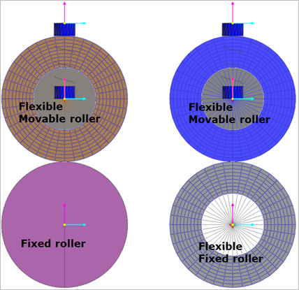
Figure 24.60 Flexible movable roller
24.5.2.1. Modeling Options
The user can create the flexible movable roller group as follows.
Fixed Roller Group, Direction, Radius, WithDialog
Fixed Roller Group: Selects a fixed roller group.
Direction: Defines the position of the movable roller group with respect to the fixed roller group.
Radius: Defines a radius of the flexible movable roller group.
WithDialog: Modifies the property for the flexible movable roller group. The flexible fixed roller group is created with clicking OK.
Fixed Roller Group, Direction, Radius, Distance, WithDialog
Fixed Roller Group: Selects a fixed roller group.
Direction: Defines the position of the flexible movable roller group with respect to the fixed roller group.
Radius: Defines a radius of the flexible movable roller group.
Distance: Defines an initial gap between the flexible movable roller group and the movable roller group.
WithDialog: Modifies the property for the flexible movable roller group. The flexible fixed roller group is created with clicking OK.
24.5.2.2. Properties
The properties dialog box of the flexible movable roller has five tabs.
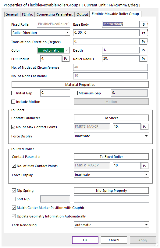
Figure 24.61 Flexible Movable Roller Group property page [Flexible Movable Roller Group page]
Fixed Roller: Displays the name of connected fixed roller.
Base Body: Defines the base body of translational joint.
Roller Direction: Defines the position of movable roller with respect to the fixed roller. The user can use input this value as Parametric Point.
Roller Angle(PV:R): Defines the angle position of movable roller with respect to the fixed roller. The angle unit is radian in case of using Parametric Value.
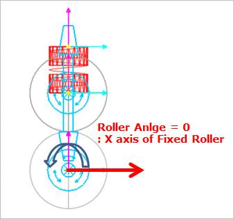
Figure 24.62 Definition of roller angle
Translational Direction (Degree): Defines the translation direction. Default is 0.0 degree. The input angle range is from -90.0 to 90.0 degree. (Maximum Gap, Initial Gap, and Soft Nip functions are not related with this Translational Direction.)
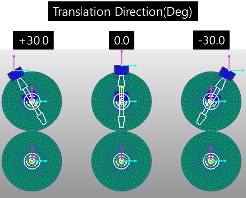
Figure 24.63 Effect of the Translation Direction
Color: Defines the color of Shell4 element.
Depth: Defines the thickness of Shell4 element.
FDR Radius: Defines the radius of inner circle.
Roller Radius: Defines the radius of outer roller.
No. of Nodes at Circumference: Sets the number of nodes in the circumferential direction. This data cannot be changed after creation.
No. of Nodes at Radial: Sets the number of nodes in the radial direction. This data cannot be changed after creation.
Material Properties: Sets the user can change the material properties. If the user wants to check the detail information, refer to Flexible Information.
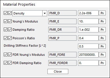
Figure 24.64 Material Properties dialog box for the flexible movable roller
Initial Gap: Defines the initial gap between the fixed roller and the flexible movable roller.
Maximum Gap: Defines the maximum gap between the fixed roller and the flexible movable roller.
Include Motion: Defines the angular motion of flexible movable roller. The user can define the roller displacement, velocity and acceleration by using Expression. Refer to Motion.
Contact Parameter: Contact Parameter: Allows the user to modify contact parameters by clicking To Sheet and To Fixed Roller.
To Sheet: In this dialog box, the user can modify the contact parameters of contact forces applied between the sheet and the fixed roller. Refer to Contact formulas for MTT2D.
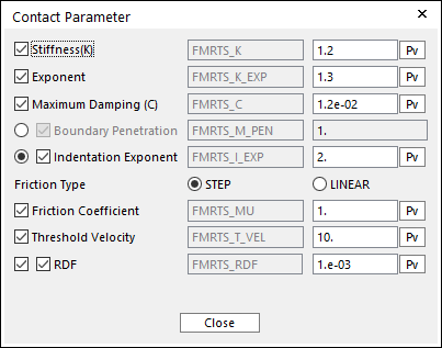
Figure 24.65 Contact Parameter dialog box
To Fixed Roller: In this dialog box, the user can modify the contact parameters of contact forces applied between the movable roller and the fixed roller. Refer to Contact formulas for MTT2D.
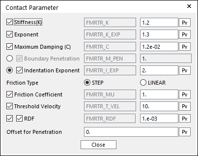
Figure 24.66 Contact Parameter dialog box
- No. of Max Contact Points (“To SHEET” and “To FIXED ROLLER”) :
Defines the number of max contact point for output. User can define this value from 1 to 5000. This value only affects Force Display and RPLT data about the contact points. The default value is 10.
- Force Display (“To SHEET” and “To FIXED ROLLER”) :
Graphically displays the all contact force vectors (the sum of the normal and tangential contact force) at each contact point up to the No. of Max Contact Point.
Nip Spring: If the user checks the check box, then the spring is activated on the flexible movable roller. The user can modify the Nip spring property by clicking Nip Spring Property.
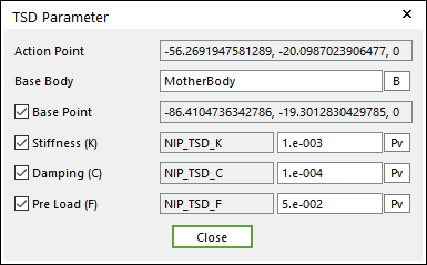
Figure 24.67 TSD Parameter dialog box
Soft Nip: Defines the motion of translational joint to the dummy body called RAR using Expression. (Refer to Soft Nip)
Match Center Marker Position with Graphic: If this is checked, the position of center marker in the flexible movable roller body always matches with the center of roller geometry.
Update Geometry Information Automatically: If this option is unchecked, the position and orientation of the geometry constituting the group are not updated depending on variables in the property page. So, after executing Extract function, this option is unchecked.
24.5.2.2.1. Output
The user can define the output nodes. If the user sets the output nodes, the solver provides the position, velocity, acceleration, stress, strain, contact force and elastic force in the RPLT file.
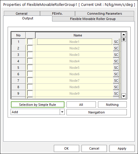
Figure 24.68 Flexible Movable Roller Group property page [Output page]
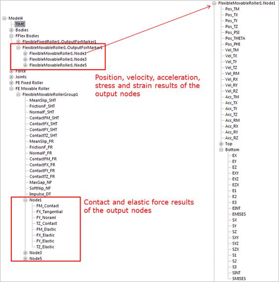
Figure 24.69 RPLT result using the output function of a flexible movable roller