6.1.4.3.3. Outline Surface
It allows the user to create a surface geometry by using more than two user-defined outline curves. At that time, the number of point data of outline curves should be the same.
6.1.4.3.3.1. Modeling Options
The user can create a surface geometry by the following procedure.
MultiOutlineCurve
MultiOutlineCurve: Selects several outline curves. At that time, the number of data of those should be the same.
6.1.4.3.3.2. Properties
The user can modify the geometry information using the Outline Surface Geometry property page.
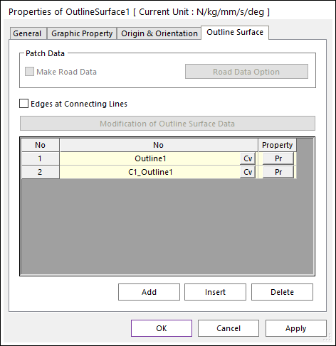
Figure 6.68 Outline Surface property page
Patch Data: Specifies the patch data for Road. This function is activated in Ground Mode.
Make Road Data: If this option is checked, Road data is created with clicking Apply or OK in Outline Surface property page. In this case, factors provided in Road Data Option to define the facet size are used as default values.
Patch Road Option: Specifies factors to define the facet size.
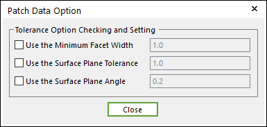
Figure 6.69 Patch Data Option dialog box
Use the Minimum Facet Width: Defines the minimum width of any side of a facet. If this option is unchecked, Parasolid calculates an appropriate value based on the size of the face box. The user can input the value from 0 to 1.
Use the Surface Plane Tolerance: Defines the maximum distance between the mid-plane of a facet and its original face entity. If this option is unchecked, Parasolid calculates appropriate tolerance values internally. To understand this function, refer to the below figure. The user can input the value from 0 to 1.
Use the Surface Plane Angle: Defines the maximum angle (in radians) which is permitted between the surface normals at any two positions on the surface which lie within the facet boundary. If this option is unchecked, Parasolid calculates appropriate tolerance values internally. To understand this function, refer to the below figure. The user can input the value from 0 to 1.
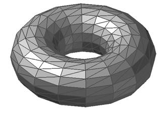
Figure 6.70 Unchecking Use the Surface Plane Tolerance and Use the Surface Plane Angle options
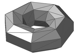
Figure 6.71 Use the Surface Plane Tolerance = 1 and Use the Surface Plane Angle = 1
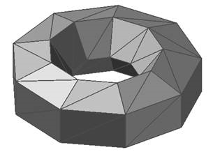
Figure 6.72 Use the Surface Plane Tolerance = 0.0002 and Unchecking Use the Surface Plane Angle option
Edges at Connecting Lines: Edges are created on all lines connecting outline points. If unchecked, edges are not created on the continuously connected parts.
Modification Of Outline Surface Data: Shows the curve data and point data that make up the surface geometry. And then the user can modify the outline surface data. Please note that any changes are applied only to the surface data, not to the original curve data.
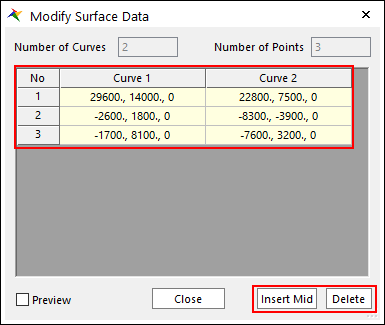
Figure 6.73 Modify Surface Data dialog box
Insert Mid: Add a curve centered between the selected curve and the curve on the left to the column directly next to the left.
Delete: Previews the surface to be created on Working Window.
Preview: Preview the points on the surface to be created on Working Window.