22.3.2.1. User-defined Program Host Mode
22.3.2.1.1. Step I (In RecurDyn)
Step to open the RecurDyn model
The model is provided in the RecurDyn installation directory <Install Dir>\Help\Examples\GCoSim\External\CPP\.
Create a new working directory.
Copy the RecurDyn model(mouse.rdyn) from the directory paste to the newly created working directory.
Run RecurDyn.
Open the RecurDyn model. And then, the mouse model appears in the working window.
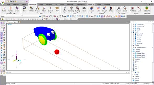
Figure 22.67 Mouse model
Step to verify the mechanical system model
Prior to applying a control system to this model, make sure that the mouse model runs without any errors.
Select Dynamic/Kinematic icon of the Simulation group in the Analysis tab.
Enter End time and Step.
Click Simulate.
Save the RecurDyn model and terminate the RecurDyn program.
22.3.2.1.2. Step II (In RecurDyn)
Step to identify GPlant inputs
The input of interest is the single rotational axial force is applied to the wheel Revolute Joint to move the mouse.
Click the GPlant_In icon of the Control group in the Communicator tab. The GPlant Input List dialog box appears as shown in Figure 22.68.
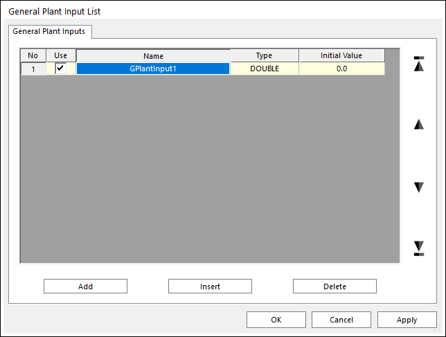
Figure 22.68 GPlant Input List dialog box
Add a GPlant input as the name of the actuator. For more information, click here.
Add an expression function as a following figure.
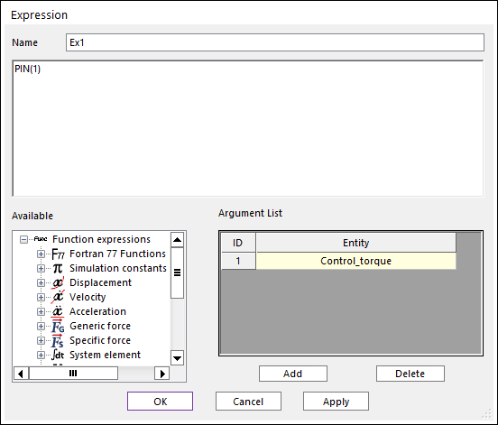
Figure 22.69 Expression dialog box
Open the dialog box of Rotational Axial force by double clicking RotationalAxial1 in the Database window. And then input the expression function defined in the upper step.
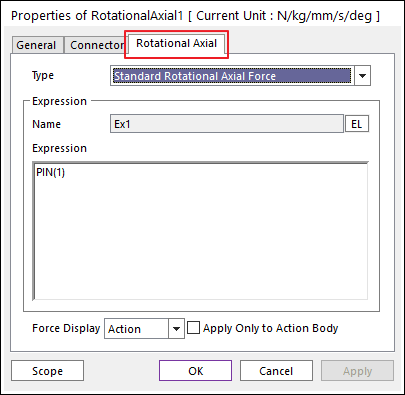
Figure 22.70 Rotational Axial force dialog box
Step to identify GPlant outputs
The output of interest is the displacement and velocity between the ball and the Mouse body pointer. This distance is in the X direction.
Click the. GPlant_Output icon of the Control group in the Communicator tab. The GPlant Output List dialog box appears as shown in Figure 22.71.
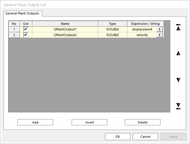
Figure 22.71 GPlant Output dialog box
Add GPlant outputs as expression functions. For more information, click here. At this dialog, the defined expression functions are as following figures.
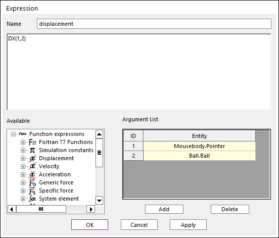

Figure 22.72 Expression dialog box
Step to select the interface option
Save the RecurDyn model in the normal fashion.
Click the General icon of the Control group in the Communicator tab. The CoSim dialog box appears.
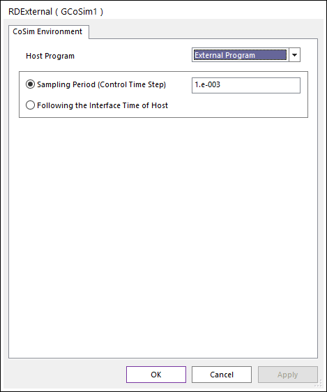
Figure 22.73 External dialog box
Edit Sampling Period (Control Time Step).
Click OK.
Close the RecurDyn Program after save the RecurDyn model.
22.3.2.1.3. Step III (In User-defined Program)
Step to design control system
Run the Microsoft Visual Studio.
Create a new project from the File Menu.
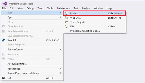
Figure 22.74 File Menu
Open the New Project window as shown.
Select Win32 Console Application.
Define the Location as new working directory.
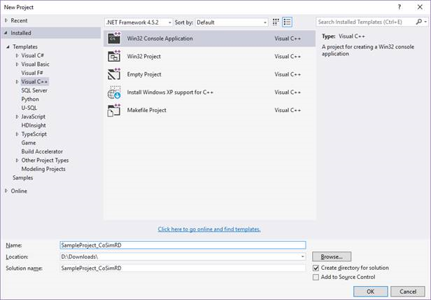
Figure 22.75 New Project dialog box
Select the option as Empty project of the Console Application.
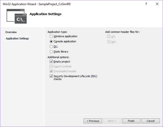
Figure 22.76 Select the option of Console Application
The sample test code is provided in the RecurDyn installation directory <Install dir>\Help\Examples\GCoSim\External\CPP\.
Copy the sample test code(GCoSim_RDClient.cpp) from the directory paste to the working directory.
The library and DLL files are provided in the RecurDyn installation directory <Install dir>\Toolkits\Controls\GCoSim\External\.
Copy the library file(RDGCoSim.lib/RDGCS_ClientAPI.lib) and DLL file(RDGCoSim.dll/RDGCS_ClientAPI.dll) from the directory paste to the working directory.
Note
If you want to see functions provided by the library file(RDGCoSim.lib/RDGCS_ClientAPI.lib) and DLL file(RDGCoSim.dll/RDGCS_ClientAPI.dll), click here.
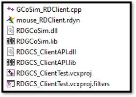
Figure 22.77 New working directory
Add an example source file (GCoSim_RDClient.cpp) from a working directory.
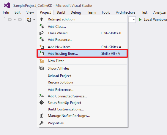
Figure 22.78 Add an example source file
Change the solution platform to x64.
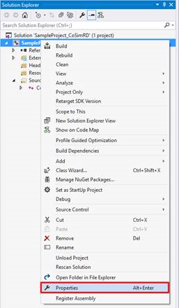
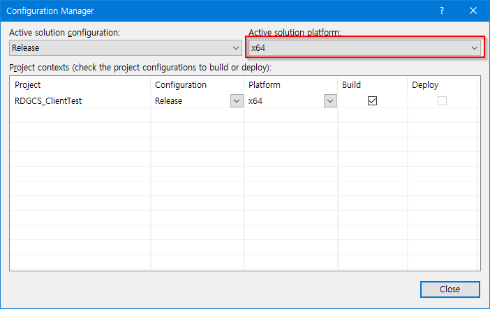
Figure 22.79 Change the platform
Link the RDGCoSim.lib/RDGCS_ClientAPI.lib in your project. (This file contains the interface functions such as a RunRecurdyn, CommunicateRecurDyn, FreeCosimMemory functions)
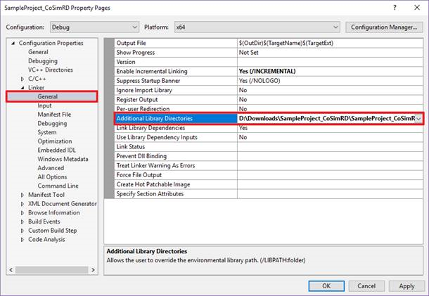
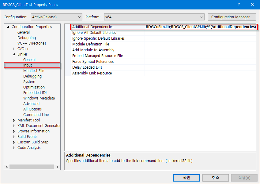
Figure 22.80 Link Library Files
Implement your own codes in this source file (GCoSim_RDClient.cpp).
Create your EXE file by using the Rebuild Solution option of Visual Studio.
=============== Interface Function ==========================
- RunRecurDyn:
char* chInterface
int iNPin
int iNPout
char* chDirectory
char* chmodelname
double controltimestep
double endtime
int plotStep
int staticanalysis
int RecurDynShow
int RecurDynAni
int* seqIf
int* errorcode
This function must be called only one before interfacing.
Parameter Name |
Unit |
IO type |
Type |
Description |
|---|---|---|---|---|
chInterface |
[-] |
Input |
char* |
The unique Name for Interface to each other. |
iNPin |
[-] |
Input |
int |
The Number of Plant Input. |
iNPout |
[-] |
Input |
int |
The Number of Plant Output. |
chDirectory |
[-] |
Input |
char* |
Is the RecurDyn program installed directory. |
chmodelname |
[-] |
Input |
char* |
Is the RecurDyn model name |
controltimestep |
[-] |
Input |
double |
Is the interface step |
endtime |
[-] |
Input |
double |
Is the simulation end time |
plotStep |
[-] |
Input |
int |
Is the RecurDyn request step |
staticanalysis |
[-] |
Input |
int |
0: dynamic analysis 1: static analysis |
RecurDynShow |
[-] |
Input |
int |
0: no 1: show the RecurDyn program |
RecurDynAni |
[-] |
Input |
int |
0: no 1: show the animation |
seqIf |
[-] |
Output |
int |
The ID (sequence) of created interface. |
errorcode |
[-] |
Output |
int |
0: no error 1: The model can’t be simulated. 2: RecurDyn can’t be executed. |
- CommunicateRecurDyn:
int seqIf
double sim_time
int iNPin
int iNPout
double* dPIN
double* dPOUT
double* rd_time
int* errorcode
This function must be called once at interface time step.
Parameter Name |
Unit |
IO type |
Type |
Description |
|---|---|---|---|---|
seqIf |
[-] |
input |
int |
The ID (sequence) of created interface. |
sim_time |
[-] |
Input |
double |
Is the simulation time |
iNPin |
[-] |
Input |
int |
Is the number of plant input |
iNPout |
[-] |
Input |
int |
Is the number of plant output |
dPIN |
[-] |
Input |
double |
Is the values of plant input |
dPOUT |
[-] |
Output |
double |
Is the values of plant output |
rd_time |
[-] |
Output |
double |
Is the RecurDyn simulation time |
error code |
[-] |
Output |
int |
0: no error 1: The model is abnormally stopped 2: The RecurDyn don’t respond. 3: Interface time don’t match. |
- FreeCosimMemory:
int seqIf : The ID (sequence) of created interface, input type.
This function must be called only one after interfacing.
22.3.2.1.4. Step IV (In User-defined Program)
Step to do the co-simulation
Copy the built EXE and library and DLL files to the working directory of the RecurDyn model.
Note
The built EXE and library and DLL files should be in the same folder with the RecurDyn model.
Execute the built EXE file to start the simulation.
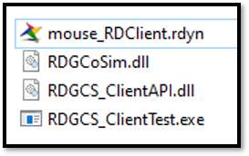
Figure 22.81 Working directory
22.3.2.1.5. Step V (In RecurDyn)
Step to see the Animation Result
Execute RecurDyn.
Open the mouse.rdyn and then import the RAN file to see the animation.
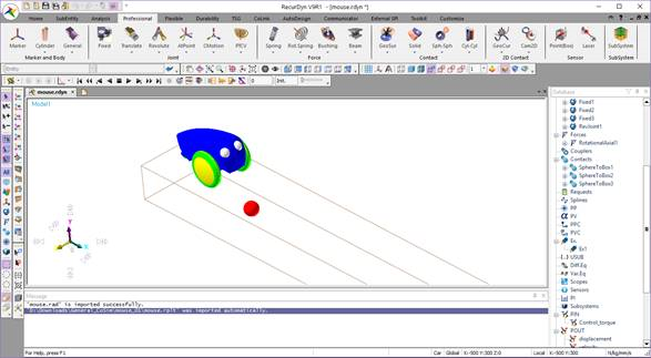
Figure 22.82 Show the animation
Step to see the Plot Result
To plot the output data, click the Result icon of Plot group in Analysis tab.
Import the RPLT file to see the plot data.
Expand the GPlant Input item in the database window on the right side. Expand the Control_torque. Double-click on Value in the section and adjust the label and axes to get the plot below.
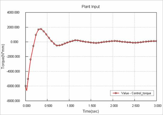
Figure 22.83 Plot of Value-Control_torque
Expand the GPlant Output item. Expand the displacement and velocity and double-click on each Value.
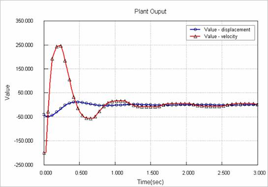
Figure 22.84 Plot of Value-displacement and Value-velocity