17.1.1. Calculation of the displacement
The displacement of an arbitrary node p at simulation time t is calculated with the following equation. In order to remove the rigid modes, the displacement is calculated using the three nodes reference frame. And, in order to describe the deformation, the initial displacement is subtracted at each simulation time.
\(\mathbf{d}_{p,t}'=\mathbf{A}_{r,t}^T(\mathbf{r}_{p,t}-\mathbf{r}_{r,t})-\mathbf{A}_{r,0}^T(\mathbf{r}_{p,0}-\mathbf{r}_{r,0})\)
- Where,
- \(\mathbf{A}_{r,t}\) is the orientation matrix made by three reference nodes at the simulation time t.\(\mathbf{r}_{p,t}\) is the position vector of the node p at simulation time t.\(\mathbf{r}_{r,t}\) is the first node position of reference nodes at simulation time t.\(\mathbf{A}_{r,0}\) is the orientation matrix made by three reference nodes at the initial time.\(\mathbf{r}_{p,0}\) is the position vector of the node p at initial time.\(\mathbf{r}_{r,0}\) is the first node position of reference nodes at initial time.
The reference frame is defined using the three nodes.
The first node position is defined as the position reference.
The orientation is defined as the following figure.
The local x direction is the same direction vector pointed from first node position to second node position.
The direction vector from first node position to third node position is located in the local X-Y plane.
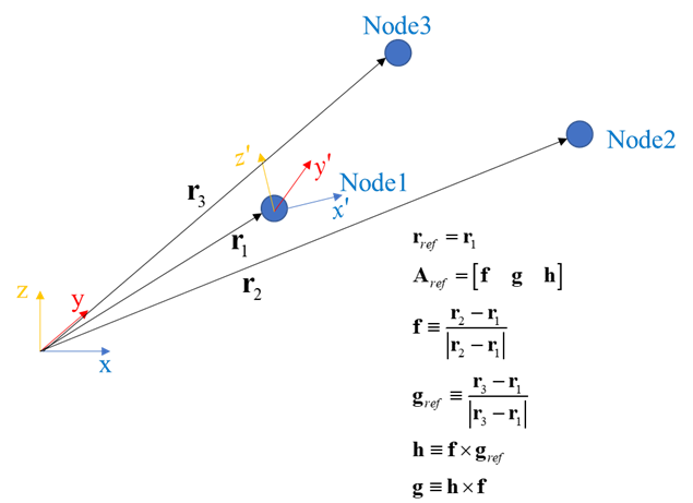
Figure 17.2 Reference Frame using the three reference nodes