The Sphere To FSurface Contact generates a contact force between a FFlex body and a Rigid body.
The FFlex body is the base body of contact.
The rigid body is the action body.
The Patch Set of the base contact surface must be defined before creating the contact.
The patch set should be generated on the FFlex body.
The contact force is generated with the compliance characteristics allowing to the penetration.
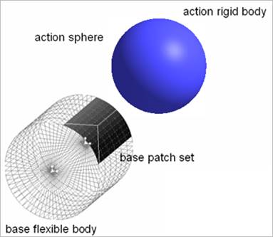
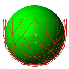
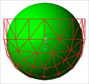
The action contact geometry is defined as a sphere and the base contact surfaces are approximated as multi triangular or rectangular patches according to the finite element as shown in Figure 9.142.
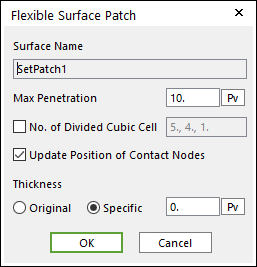
Max Penetration: Is the maximum penetration. If the penetration is greater than this value, then the contact force is not generated.
No. of Divided Cubic Cell: The number of cubic cells dividing a contact boundary box. This value is automatically calculated. But if it needs, the value can be modified by the user.
Update Position of Contact Nodes: A flag whether the position of nodes belong to the patch set is updated during a simulation. If your system is the small deformation problem and this option is unchecked, then the solving time can be improved.
Thickness Definition: Thickness of patch is defined in the Original or Specific type. The original type uses thickness of shell property. The specific type uses User-defined thickness.
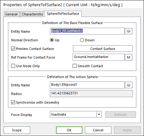
Ref. Frame for Contact Surface: The contact force applied on the base body is reported as a force generalized on the defined marker.
If the marker is not defined, the default is Ground.Inertia Marker.
Use Node Only: Nodes of base flexible contact surface are only used to generate the contact force of Sphere To FSurface contact.
Generally, this option can be very useful for accuracy and solving speed in the following case.
If the user does not use this option, the contact is applied as patch shape only.
If the user uses this option, the contact is applied as flexible body shape more correctly.
Smooth contact: Is to use the curve surface on base patch set.
So, if this option is used, the contact is continuously applied on the flexible surface.
Definition of the Action Sphere
Entity Name: Defines the name of action patch set. The action patch set is dispatched from the screen by clicking Gr.
Radius: Is the radius of action sphere. This value is automatically determined by the radius of the action geometry but if you turn off the Synchronize with Geometry option, you can directly input the radius or change it as the parametric value by clicking PV.
Synchronize with Geometry: If this option is checked, the contact radius of circle or sphere is automatically defined with that of the specified graphic.
Force Display: You can graphically display the resultant force vector on the view window.
Refresh: When the action or base contact patch set is changed, you can refresh the preview of information of specified contact patch set as using this function.