41.3.3. Property
The MF-Tyre/MF-Swift 6.1 is set up in a modular way and allows the user to independently set the operating mode of the Magic Formula, Tire dynamics and Contact method.
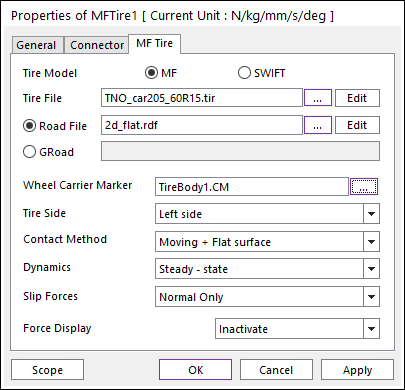
Figure 41.24 MFTire dialog box
Tire Model
MF is the MFTire.
SWIFT is the MFSwift.
Tire File
The tire property file (*.tir) contains the parameters of the tire model.
Sample tire property files are provided with the installation.
The file is subdivided in various sections indicated with square brackets.
Each section describes a certain aspect of the tire behavior.
Explanation of Parameters in the tire property file is in the MF-Tyre & MF-Swift 6.1 User Manual.
Road File
The user can use the TNO Road File (*.rdf). MFTire supports relatively several simple road surfaces offered by TNO. To see more information, refer to Road Data File.
If the user wants to see the shape of road file linked, import the road file (*.rdf) linked in the Body or the Ground Edit Mode.
GRoad
The user can import the TNO Road file (*.rdf) as shell geometry in the body or the ground edit mode and select the imported shell geometry by clicking Gr.
This option supports only the Flat Road Type. Also Contact Method is automatically changed as Moving + Flat Surface.
It is useful to do modeling Moving Ground. To see more information, refer to Moving Ground at Modeling Tips.
Moving Ground: The road moves without being fixed.
The Road of Moving Ground is GRoad shape imported from the TNO RDF file.
Wheel Carrier Marker
Wheel Carrier Marker is a wheel carrier axis system in which the kinematic inputs are expressed to calculate Tire forces.
Tire Side
A Magic Formula tire model shows offsets and asymmetric behavior caused by conicity and/or plysteer.
In the tire property file [MODEL] -section there is a keyword TYRESIDE, which can be either “LEFT” or “RIGHT” (when missing: “LEFT” is assumed). This indicates how the tire measurement was executed.
Using the same characteristics on the left- and right-hand side of a vehicle results in the undesired asymmetrical behavior of full vehicle.
If “Tire Side” is “Left Side” and the tire is mounted on the right side of vehicle, mirroring can be applied on the tire characteristics and the total vehicle can behave symmetrically.
It is also possible to remove asymmetrical behavior from an individual tire.
Table 41.6 Tire Side Parameters
Description
Available tire model
Left Side
Is mounted on the left side of the car.
MF-Tire, MF-Swift
Right Side
Is mounted on the right side of the car
MF-Tire, MF-Swift
Symmetric
Is the symmetric tire characteristics
MF-Tire, MF-Swift
Mirrored
Is a mirrored tire characteristic
MF-Tire, MF-Swift
Contact Method
Various methods are available to calculate the tire-road contact point.
Smooth road contact should only be used on a smooth road surface profile containing a minimum wavelength larger than twice the tire radius.
For short obstacles (e.g. cleats/bumps, discrete steps, potholes) or road surfaces containing wavelength smaller than twice the tire radius, either the road contact for 2D or 3D roads should be selected.
The road contact for 3D roads works on both 2D and 3D road surfaces, but it is computationally more expensive than the road contact for 2D roads that works only with 2D road profiles.
Table 41.7 Contact Method Parameters
Description
Available tire model
Smooth + Single contact point
Is the: Smooth road contact Single contact point
MF-Tire, MF-Swift
Smooth +Circular cross section
Is the: Smooth road contact Circular cross section (motorcycle tires)
MF-Tire, MF-Swift
Moving + Flat surface
Is the: Moving road contact Flat surface
MF-Tire, MF-Swift
2D road
Is the road contact for 2D roads (using travelled distance)
MF-Swift
3D road
Is the road contact for 3D roads
MF-Swift
Dynamics
Depending on the frequency range of interest more details on the dynamic behavior of tire is included. In the case of a steady-state evaluation no dynamic behavior is included.
“Linear transient effects” indicates that the tire relaxation behavior is included using empirical relations for the relaxation lengths.
In the “Nonlinear transient effects” mode, a physical approach is used in which the compliance of tire carcass is considered to determine the lag.
This approach correctly accounts for the tire property that the lag in the response to wheel slip and load changes diminishes at higher levels of slip.
This approach is fully compatible with the MF-Swift theory.
“Rigid ring dynamics” refers to a detailed dynamic model (MF-Swift), where the tire belt is modeled as a separate rigid body.
Finally, “initial statics” refers to finding the static equilibrium of tire belt (rigid ring/body) at the start of simulation.
Table 41.8 Dynamics Parameters
Description
Available tire model
Steady-state
Is the steady-state evaluation (< 1 Hz)
MF-Tire, MF-Swift
Transient linear
Is the transient effects included, tire relaxation behavior (< 10 Hz, linear)
MF-Tire, MF-Swift
Transient nonlinear
Is the transient effects included, tire relaxation behavior (< 10 Hz, nonlinear)
MF-Tire, MF-Swift
Rigid ring
Is the rigid ring dynamics included (< 100 Hz, nonlinear)
MF-Swift
Slip forces
When evaluating the Magic Formula it is possible to switch off parts of the calculation. This is useful when e.g. debugging a vehicle model, or if only in-plane tire behavior is required.
Table 41.9 Slip Forces Parameters
Description
Available tire model
Normal only
Allows no Magic Formula evaluation (Fz only)
MF-Tyre, MF-Swift
Longitudinal only
Allows longitudinal forces/moments only (Fx,My)
MF-Tyre, MF-Swift
Lateral only
Allows lateral forces/moment only (Fy,Mx,Mz)
MF-Tyre, MF-Swift
Uncombined
Allows uncombined forces/moment (Fx,Fy,Mx,My,Mz)
MF-Tyre, MF-Swift
Combined
Allows combined forces/moment (Fx,Fy,Mx,My,Mz)
MF-Tyre, MF-Swift
Combined +turn slip
Allows combined forces/moment (Fx,Fy,Mx,My,Mz) + turn slip
MF-Swift
Note