26.2.4. Arc Guide
An arc guide is dependent on a guide part. If an arc guide is created, a workpiece to arc contact is automatically created. Its contact type can be represented as a sphere to extruded arc contact. As shown in Figure 26.14, the user first should define whether the contact direction is up or down of the guide. When a sheet body is contacted with the arc guide, the plus normal direction is in up or down direction of a relative position vector from the arc reference position to the center point of the sheet body. The tangent direction can be determined from the specified normal and depth directions by the right hand rule. The plus direction of Guide velocity is determined as the plus tangential direction.
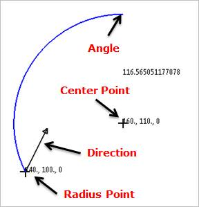
Figure 26.14 Arc Guide
26.2.4.1. Modeling Options
The user can create an arc guide as follows.
Point, Point, Direction, Angle
Point: Selects a point to define the center of the arc guide.
Point: Selects a point to define the starting point on the circumference of the arc guide. The distance between the first point and the second point becomes a radius of the arc guide.
Direction: Defines a direction for revolution of the arc guide.
Angle: Defines a revolution angle of the arc guide.
Point, Point, Direction, Point
Point: Selects a point to define the center of the arc guide.
Point: Selects a point to define the starting point on the circumference of the arc guide. The distance between the first point and the second point becomes a radius of the arc guide.
Direction: Defines a direction for revolution of the arc guide.
Point: Selects a point to define the ending point on the circumference of the arc guide. The point is constrained to be at a constant distance from the center of the arc guide.
GuideMotherBody, Point, Point, Direction, Angle
GuideMotherBody: Selects a body to define the parent body of the arc guide.
Point: Selects a point to define the center of the arc guide.
Point: Selects a point to define the starting point on the circumference of the arc guide. The distance between the first point and the second point becomes a radius of the arc guide.
Direction: Defines a direction for revolution of the arc guide.
Angle: Defines a revolution angle of the arc guide.
Point, Point, Point
Point: Selects a point to define the center of the arc guide.
Point: Selects a point to define the starting point on the circumference of the arc guide. The distance between the first point and the second point becomes a radius of the arc guide.
Point: Selects a point to define the ending point on the circumference of the arc guide.
26.2.4.2. Properties
The user can modify properties for the arc guide such as geometry information, contact characteristic using GuideArc property page.
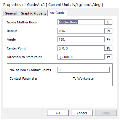
Figure 26.15 GuideArc property page
Guide Mother Body: Selects the mother body of arc guide by clicking B.
Radius: Defines the radius of arc guide.
Angle: Defines the angle of arc guide.
Center Point: Defines the center point of arc guide.
Direction to Start Point: Defines the direction to the start point of arc guide.
Imaginary Circle Edge: Defines an imaginary Circle Edge on start and/or end point of Arc Guide. The imaginary Circle Edge is a circle shape and located start/end point. And the center point of imaginary Circle Edge is located negative direction of contact (normal) direction. User can see the imaginary Circle Edge by clicking Preview.
Edge: Defines Enable(Checked) or Disable(Unchecked) on the Start and/or End point.
Radius: Defines a radius of the imaginary Circle Edge. The user can set a connection with SPV value.
No. of Inner Contact Points: Defines the additional contact points in one workpiece.
Contact Parameter: Modifies the parameters of contact between assembly (web) and the arc guide. For more information, click here.