2.2.8.5. Cutting Plane
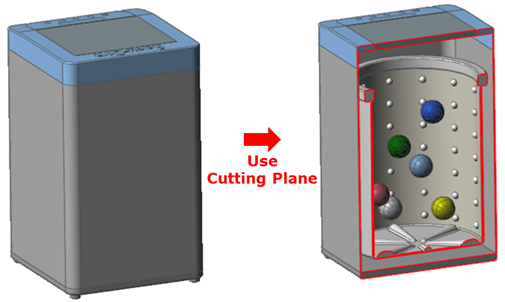
Figure 2.76 Useful Cutting Plane
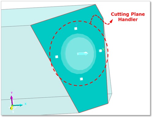
Figure 2.77 Cutting Plane Handler
Coordinate of Cutting Plane
The coordinate of Cutting Plane is decided by two vectors.
Vector 1: Defines as the first point and the second point.
Vector 2: Defines as a normal direction of Working Plane.
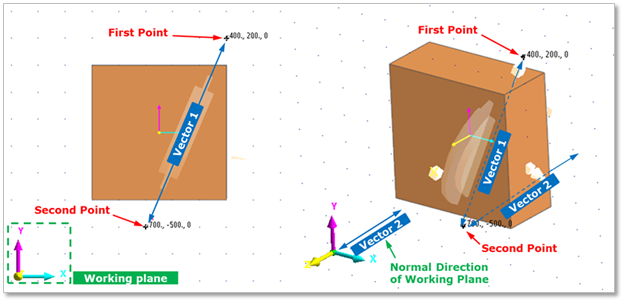
Figure 2.78 Define the coordinate of Cutting Plane
The size of Cutting Plane is infinite to all directions except the normal direction of Cutting Plane.
Figure 2.79 Size of Cutting Plane
CM of Cutting Plane
CM of Cutting Plane does not exist separately, but Cutting Plane Handler itself is a center marker of Cutting Plane.
Figure 2.80 Cutting Plane Handler and CM
+X: +Normal direction of Working Plane
+Y: Direction as second point from first point of Cutting Plane Modeling Option (“Point, Point, WithDialog”)
+Z: Right hand rule
Using Cutting Plane Handler
The user can modify the cross section by controlling Cutting Plane Handler.
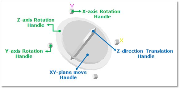
Figure 2.81 Definition of Cutting Plane Handler
Translation
XY Plane: To click and drag the XY-plane move Handle can move the cross section in the XY Plane of Cutting Plane Handler.

Figure 2.82 Move in the XY plane
Z-axis: To click and drag the Z-direction Translation Handle can translate the cross section along the Z axis of Cutting Plane Handler.
Figure 2.83 Translate along the Z axis
Rotation
X-axis: To click and drag the X-axis Rotation Handle can rotate the cross section by the X axis of Cutting Plane Handler.
Figure 2.84 X-axis Rotation of Handler
Y-axis: To click and drag the Y-axis Rotation Handle can rotate the cross section by the Y axis of Cutting Plane Handler.
Figure 2.85 Y-axis Rotation of Handler
Z-axis: To click and drag the Z-axis Rotation Handle can rotate cross section by the Z axis of Cutting Plane Handler.
Figure 2.86 Z-axis rotation of Handler
Using Cutting Plane Handler Dialog
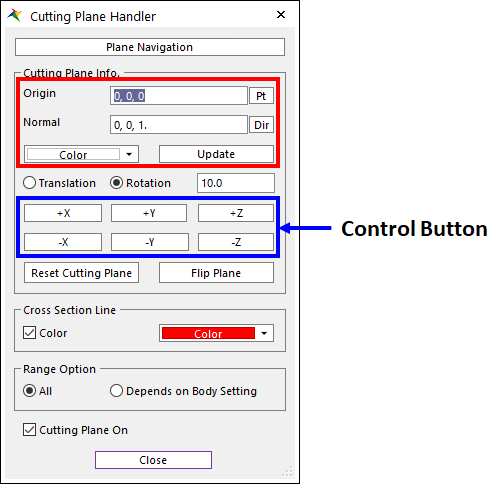
Figure 2.87 Cutting Plane Handler dialog box
Plane Navigation: Navigates the plane.
Origin: Defines the Origin of Cutting Plane.
Normal: Defines the Normal Vector of Cutting Plane.
Color: Selects color of Cutting Plane icon displayed on Working Window.
Update: If Origin and Normal are input directly in this dialog, Update button should be clicked to apply these values for the created Cutting Plane.
Translation: If this option is selected, the created Cutting Plane is translated along the axis of the Cutting Plane CM. The user must indicate the amount of translation in the Offset Value input box. To move the entity, use Control Button.
Rotation: If this option is selected, the created Cutting Plane is rotated by the axis of the Cutting Plane CM. The user must indicate the amount of rotation in the Offset Value input box. To rotate the entity, use Control Button. This unit is degree.
Reset Cutting Plane: Resets Cutting Plane to the original origin and orientation.
Flip Plane: If the user clicks Flip Plane, the cross section is inverted.
Figure 2.88 Flip Plane Inverted
Cross Section Line
Color (Check Box): If it is checked, specified color is applied to the cross-section line. If it is not, normal drawing color is applied to the cross-section line.
Color (Color Picker): Specify a color.
Range Option
All: If it is checked, all bodies are applied by cutting plane regardless of bodies setting.
Depends on Body Setting: If it is checked, only bodies turned on Apply Cutting Plane option on Body property page or right-click menu are applied by cutting plane.
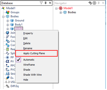
Figure 2.89 Apply Cutting Plane Option in the Right-click Menu
Cutting Plane On
If this option is checked, the user can see the applied cross section of Cutting Plane.
If this option is unchecked, go back to the original shape.
Figure 2.90 Cutting Plane OFF
Cutting Plane Preset: Preset the cutting plane of window.
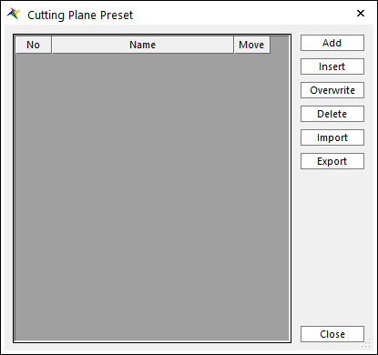
Figure 2.91 Cutting Plane Preset dialog box
No: Shows the number of cutting plane.
Name: Specifies the name of cutting plane.
Move: Move the saved cutting plane.
Add: Adds the row and save the current cutting plane.
Insert: Inserts the row and save the current cutting plane.
Overwrite: Overwrites the current cutting plane.
Delete: Deletes the row.
Import: Imports list of Cutting Plane Presets from the *.xml file.
Export: Exports list of Cutting Plane Presets to the *.xml file.