19.2.2.3.2. Properties
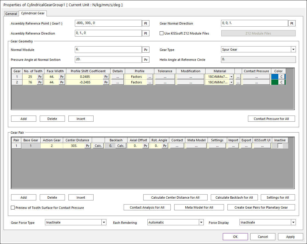
Figure 19.19 Properties of CylindricalGear dialog box
Assembly Reference Point (Gear1): Specify the reference point of bae gear for gear pair assembly.
Gear Normal Direction: Specify the normal direction of gear pairs.
Assembly Reference Direction: Specify the direction vector from gear1 center to gear2 center.
Use KISSsoft Z12 Module Files: User can import *.z12 file itself and RecurDyn automatically generates gear pair geometry according to this *.z12 file regardless of user input parameters in CylindricalGear dialog. RecurDyn does not support all parameters of *.z12 file supported by KISSsoft. So if the user wants to use *.z12 file in RecurDyn as it, this function is recommanded.
Gear Force Type: Select a gear force type for the gear pair. There are 3 types.
Inactivate: If this type is selected, there is no gear contact. An additional contact should be defined such as Gear Involute Contact.
KISSsoft Force: If this type is selected, RecurDyn co-simulate with KISSSoft directly to calculate the gear contact.
KISSsoft Force (Meta Model): If this type is selected, RecurDyn calculate the gear contact by using the meta model file.
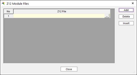
Figure 19.20 Z12 Module Files dialog box
Note
If user import *.z12 file itself, the root and flank safety should be evaluable for the *.z12 file. if not, it coule be impossible to simulate gear contact analysis.
19.2.2.3.2.1. Gear Geometry
This section is to define the geometry of the gear pair.
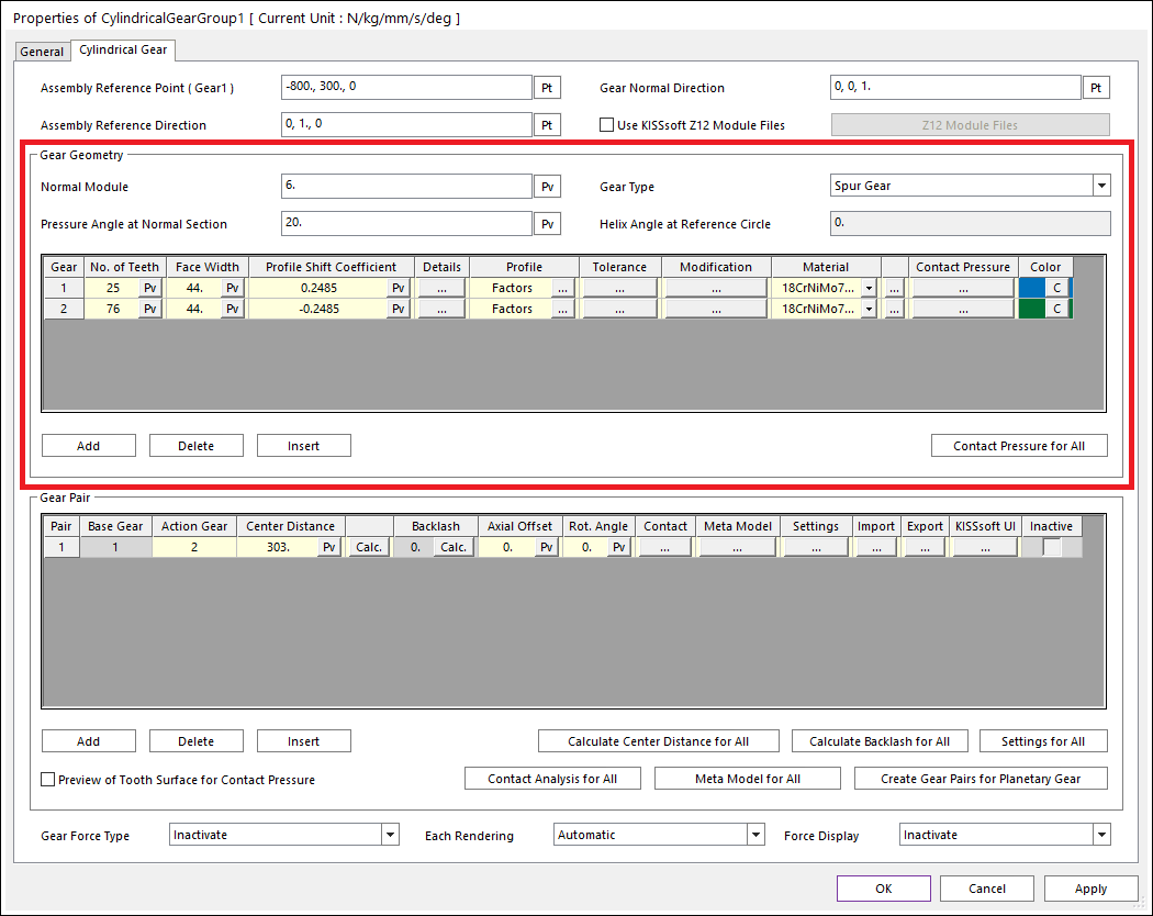
Figure 19.21 Properties of CylindricalGear dialog box (Gear Geometry)
Normal Module: Normal module is the size unit that displays how big or small a gear is. It is the ratio of the gear’s reference diameter divided by the number of teeth.
Gear Type: Three types are supported. (Spur Gear, Helix Right Hand, Helix Left Hand)
Pressure Angle at Normal Section: Normal pressure angle at the reference circle. It is defined as the angle between the pressure line and the plane tangent to the surface of the pitch. The pressure angle is 20 degrees for typical gear. For a higher number of teeth, lower pressure angle can be used to obtain higher contact ratios and insensitivity to center distance changes. Higher pressure angles improve strength and make it possible to use a fewer number of teeth without undercut. The contact ratio decreases in this situation and the radial forces increase.
Helix Angle at Reference Circle: Helix angle at reference circle. If spur gear is used, this value is zero. The helix angle determines the axial forces direction. Helical gear produces less noise than the spur gear but generates an extra bending moment and an axial force.
No. of Teeth: Number of teeth of this gear. You can create Internal Gear by setting Number of Teeth of gear2 as minus value.
Face Width: Gear face width. The face width would usually not be more than 10 to 20 times the normal module or not more than the pinion reference circle.
Profile Shift Coefficient: The distance between the production pitch circle and the tool reference line. The tool is pulled further out of the material to create a positive profile shift generating a tooth that is thicker at the root and thinner at the tip the tool is pushed further into the material to create a negative profile shift resulting in the tooth being thinner and undercutting may occur earlier. Besides the effect on tooth thickness, the profile shift coefficient also affects the sliding velocities. The total profile shift distribution affects the thickness of the tooth, sliding movements, and strength values.
Details: For external gear, Inner Diameter is diameter of hole. For internal gear, Outer Diameter is diameter of outermost side circle of gear.
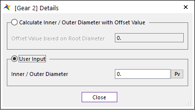
Figure 19.22 Gear Details dialog box
Calculate Inner / Outer Diameter with Offset Value : If this option is checked, Inner or outer diameter is calculated with offset value based on root diameter.
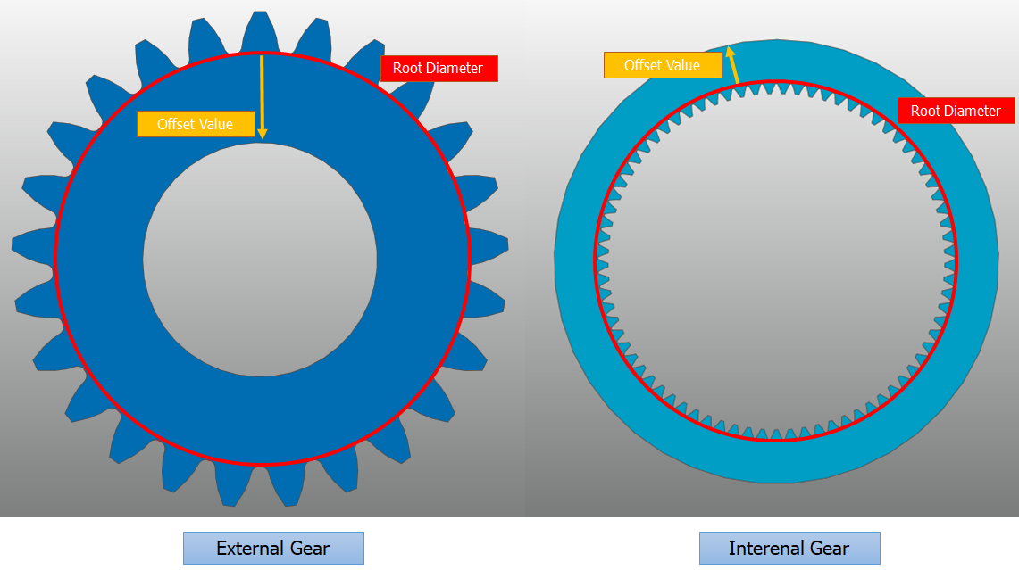
Figure 19.23 Definition of Offset Value based on Root Diameter
Profile: Tooth profile can be defined according to related parameters. There are three types of methods for defining a tooth profile. If reference profile is defined from the data base list, related parameters are updated automatically.
Factors
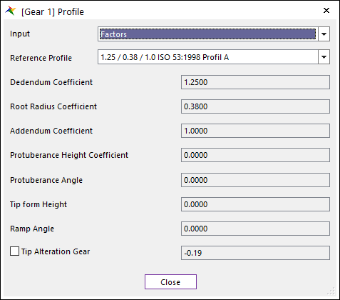
Figure 19.24 Gear Profile dialog box [Factors]
Dedendum Coefficient: Defined the cutter’s dedendum that, with a topping tool, determines the tip circle.
Root Radius Coefficient: Defines the cutter fillet radius. In a topping tool, the root radius cuts a tip rounding on the gear in most cases. The manufacturing process is simulated by KISSsoft Gear. In doing so, the effective undercut in the root of the tooth is calculated.
Addendum Coefficient: Defines cutter addendum, which defines the gear root circle.
Protuberance Height Coefficient: Defines the protuberance length, measured from the addendum. The protuberance is used as an artificial undercut to prevent a grinding notch from being created.
Protuberance Angle: This value is usually smaller than the pressure angle. However, in the case of some special cutters, it may also be larger.
Tip form Height: Defines the start of the straight flank / involute part of the tool with pressure angle. The height is measured from the tool reference line.
Ramp Angle: Defines a ramp flank or a profile modification that is present in the cutter.
Tip Alteration Gear: Tip alteration are calculated from the total profile shift to ensure that the tip clearance does not change. Tip clearance is the distance between the tip circle of one gear and the root circle of the other gear.
Tip Radius Coefficient: Tip radius means the tip radius of the cutter which determines the radius of the root of the gear. Gear root radius means the gear radius of the root filet.
Lengths: Parameters from Length input have same meaning from Factor. However, Coefficient parameter from Factor has proportional relationship with Module and Length parameter. For example, Dedendum equals Module multiplied by Dedendum Coefficient.
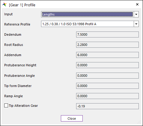
Figure 19.25 Gear Profile dialog box [Lengths]
Diameter
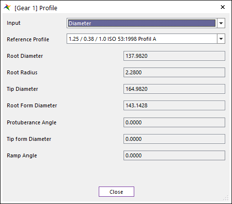
Figure 19.26 Gear Profile dialog box [Diameter]
Root Diameter: Defines the diameter of a circle around the bottom (root) of the gear tooth spaces. It is same to Root Radius in RecurDyn/Gear.
Root Radius: Defines the cutter fillet radius. In a topping tool, the root radius cuts a tip rounding on the gear in most cases. It is same to Hob Rack Radius in RecurDyn/Gear.
Tip Diameter: Defines the overall diameter of the gear.
Root Form Diameter: Defines the diameter which specifies the transition point between the usable involute profile and the fillet of the tooth.
Tolerance: The toothing geometry is calculated for a backlash-free state. A slightly smaller tooth thickness is manufactured, to prevent the gears jamming in practice. This reduction in tooth thickness is known as the tooth thickness allowances.
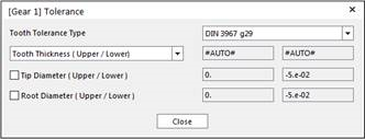
Figure 19.27 Gear Tolerance dialog box
Tooth Tolerance Type: RecurDyn provides the tolerance type KISSsoft support.
Tooth Thickness (Upper/Lower): Defines the allowance of Tooth Thickness. The upper tooth thickness allowance is the upper limit of the tooth thickness. The lower tooth thickness allowance is the lower limit of the tooth thickness. Default setting is that Tooth thickness calculated automatically.
Note
After changing the Tooth Tolerance and calculate backlash, the backlash changes with set tolerances. The backlash is calculated with several factors according to selected calculation method in KISSsoft e.g. DIN3967. After selecting the Tooth Tolerance Type such as DIN3967 h22, KISSsoft calculate Upper and Lower Allowance. With Upper and Lower Allowance, KISSsoft calculates Tooth Thickness Tolerance. (Tooth Thickness Tolerance = Upper - Lower allowance). Tooth Thickness Tolerance is taken into account for Backlash calculation. Calculated backlash is then taken into account for calculating tooth geometry.
Tip Diameter (Upper/Lower): User can specify the tip diameter allowances if a non-topping tool has been defined. In contrast, the tip allowances for a topping tool are defined from the tooth thickness allowances.
Root Diameter (Upper/Lower): Root diameter allowances are usually calculated from the tooth thickness allowances. In a gear cutting process, the gear backlash is produced by reducing the manufacturing distance of the tool. This is why the root diameter allowances depend on the tooth thickness allowances.
Note
The Gear Train dialog in RecurDyn/DriveTrain is created based on the KISSsoft User Interface. Some of the nomenclature is different from the RecurDyn/Gear. Below is the comparison of those parameters that has the same meaning but different names.
Delta Tooth Thickness from RecurDyn/Gear has similar gear geometry result with KISSsoft if its values is (Upper Tooth Thickness + Lower Tooth Thickness)/2.
KISSsoft |
RecurDyn |
Normal Module |
Module |
Pressure Angle at Normal Section |
Pressure Angle |
Helix Angle at Reference Circle |
Helix Angle |
Face Width |
Gear Width |
Profile Shift Coefficient |
Addendum Modification Coefficient |
Inner Diameter |
Hole Radius |
Dedendum Coefficient |
Dedendum Factor |
Root Radius Coefficient |
Hob Rack Radius Coefficient |
Addendum Coefficient |
Addendum Factor |
Modification
Tip Modification
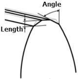
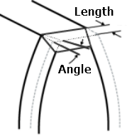
Chamfer: Define the Length and Angle of Chamfer at tip. Refer to the image below.
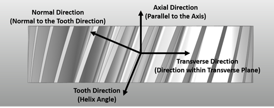
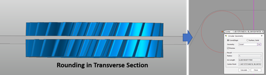
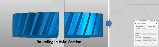
Rounding in Transverse / Axial / Normal Section: Normal direction is normal to the tooth direction. Axial direction is parallel to the axis. Transverse direction is direction within transverse plane. If the gear type is spur gear, only transverse option is available. Refer to the image below.
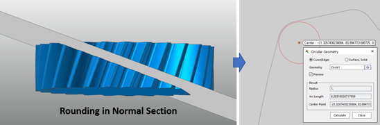
If you use Rounding in Normal Section, the user input Radius is applied in normal section. Refer to the image below.
If you use Rounding in Transverse Section, the user input Radius is applied in transverse section. Refer to the image below.
If you use Rounding in Axial Section, the user input Radius is applied in axial section. Refer to the image below.
Chamfer/Tooth End: Define the Length and Angle of Chamfer at tooth end. Refer to the image below.
Profile/Tooth Modification: For more information, click here.
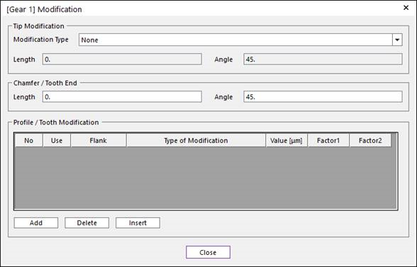
Figure 19.28 Modification dialog box
Material: The materials displayed in the drop-down lists are taken from the material data base KISSsoft support.
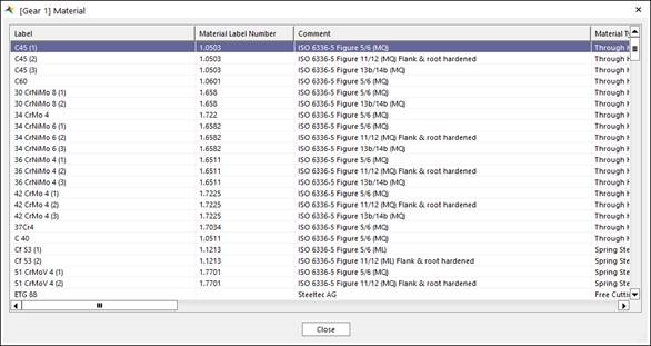
Figure 19.29 Gear Material dialog box
Contact Pressure: Define UV patch of gear tooth for contact pressure contour. For information, click here.
19.2.2.3.2.2. Gear Pair
This section is to define relation between gears.
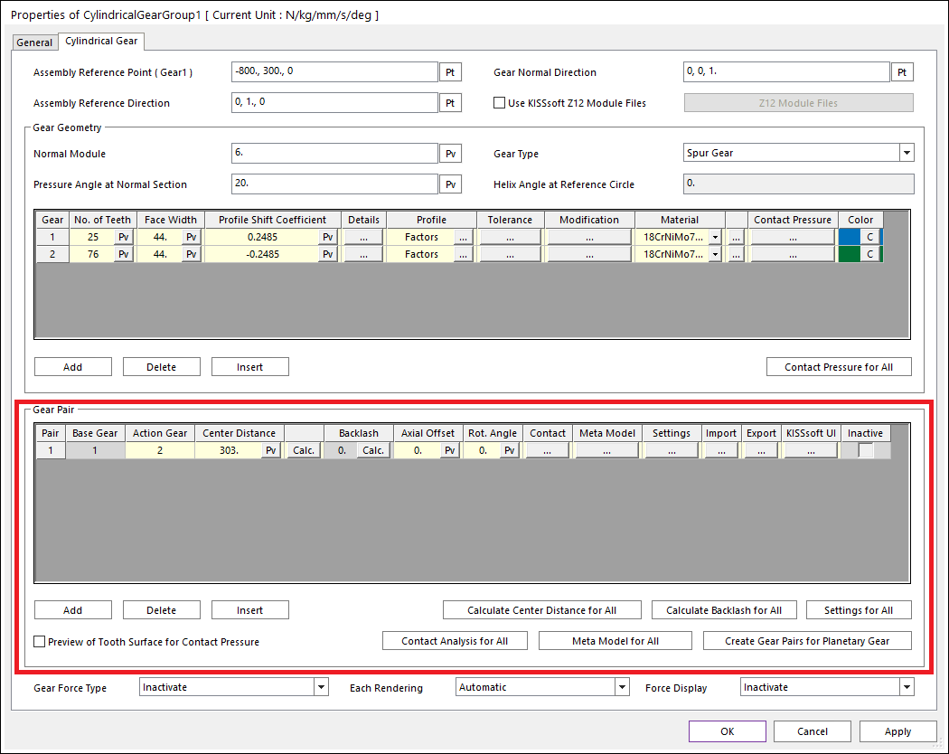
Figure 19.30 Properties of CylindricalGear dialog box (Gear Pair)
Base Gear, Action Gear: Base and action gear ID.
Backlash: A gap between the teeth when gear pair is engaged. this value can be calculated automatically by clicking Calculation.
Contact: Contact analysis is performed by discretized tooth model. Deformation theory of meshing in gear pairs developed by Weber/Banaschek can be applied to three dimensional cylindrical gears with helical gear teeth.
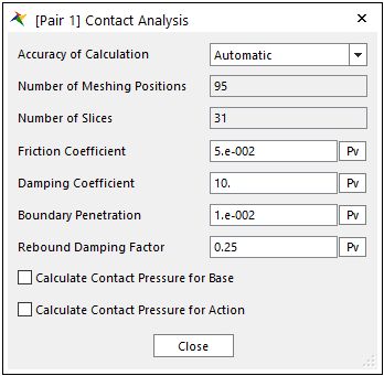
Figure 19.31 Gear Contact Analysis dialog box
Accuracy of Calculation: In automatic type, RecurDyn automatically calculate some parameters related to contact analysis. In user input case, user can input parameters in contact analysis directly.
Number of Meshing Positions: Number of meshing positions for application of deformation theory.
Number of Slices: Number of slices in order to discretize toothing model.
Friction Coefficient: Friction coefficient in contact.
Damping Coefficient: Specifies a viscous damping coefficient for the contact normal force.
Boundary Penetration: Specifies a full damping penetration. If the penetration is less than this value, the damping coefficient is calculated with the STEP function. And if the penetration is equal or greater than this value, RecurDyn uses the user-defined damping coefficient.
Rebound Damping Factor: To obtain realistic hysteric loop for energy dissipation during the contact, this rebound damping factor controls the rebound damping force when bodies are on restitution phase.
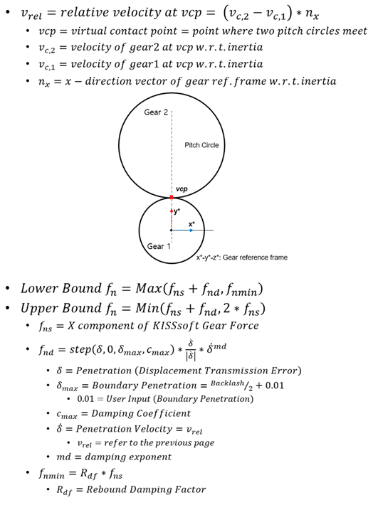
Eq.1 Equation of Damping Force
Calculate Contact Pressure for Base & Calculate Contact Pressure for Action: This is the check option whether to calculate contact pressure, sliding velocity and PV(Pressure Velocity) of gear tooth. if checked, contact pressure contour is available for the gear body checked through rigid contour in post tool. Please refer to here.
Meta Model: MetaModel is a method to make table data of gear force and use it for dynamic analysis. There are 6 variables (Rotational Angle, Penetration, Distance Error, Axial Offset, Twist, Tilt) with which we can define gear pair geometry. User can define data points for each variable and then consist of gear force table data for all data points of selected variables in binary file having gmm extension. The user can use the meta model in two ways. The first is to load and use the existing meta model file, and the other is to create a meta model file in initial stage of dynamic analysis to automatically perform the dynamic analysis using it. For information, click here.
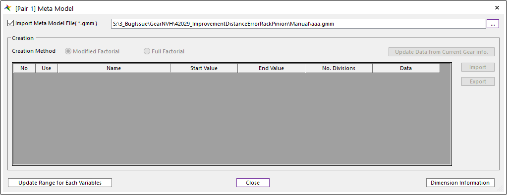
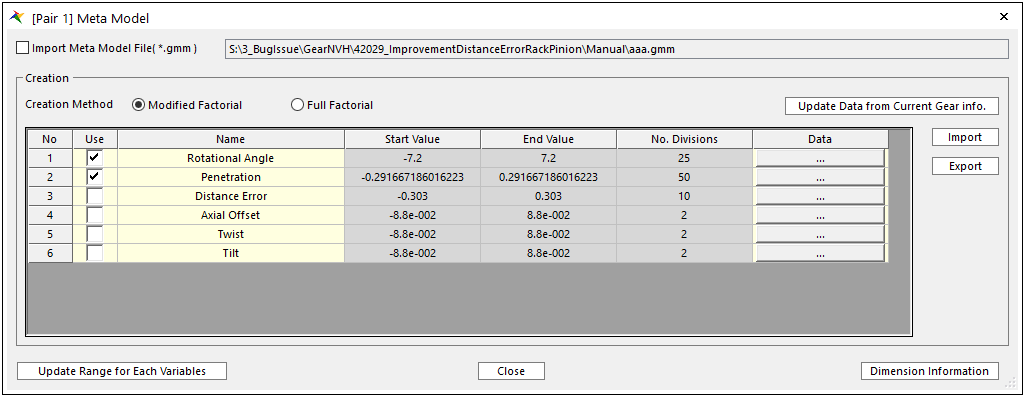
Figure 19.32 Meta Model dialog box
Import Meta Model File: User can import *.gmm file which includes gear force table data for the target gear pair. And then, RecurDyn solver uses this table data for dynamic analysis of the gear pair.
Creation: User can set table data by clicking ‘Update Data from Current Gear Info.” in default. For detail information, click here.
Axial Offset: Relative offset of action gear with respect to base gear in axial direction.
Center Distance: Distance between base gear center and action gear center. For two external gears, the center distance for external and internal gear is positive and negative for an external gear coupled with an internal gear. For internal gears, the number of teeth on the internal gear and the center distance of the axis are always negative.
Backlash: Gap between teeth of gear 1 and gear2.
Rot. Angle: Gear pair system is generated with it rotated according to this value in axial direction.
Settings: KISSsoft supports various module-specific settings. Among them, RecurDyn provides several important parameters for creating KISSSoft Gear.
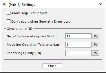
Figure 19.33 Settings dialog box
Import: User can import *.z12 file and then apply gear pair information of the *.z12 file.
Export: User can export *.z12 file including current RecurDyn gear information. User can modify some information using this *.z12 file in KISSsoft GUI in detail and then, import it RecurDyn again.
KISSsoft UI: User can open the KISSsoft UI by clicking this button. Detail modification can be performed by KISSsoft UI.
Inactive: This option can be activated when Gear Force Type is KISSSoft Force or KISSSoft Force(Meta Model). So, If this option is used, a gear force of selected gear pair is inactivated.
Calculate Center Distance for All: If this function is used, user can calculate center distance for all gear pairs.
Calculate Backlash for All: If this function is used, user can calculate backlash for all gear pairs.
Preview of Tooth Surface for Contact Pressure: If this option is checked, the UV patches for gear tooth for contact pressure contour are shown on the Working Window as shown in the Figure 19.34. It is defined in the contact pressure tab in the gear geometry.
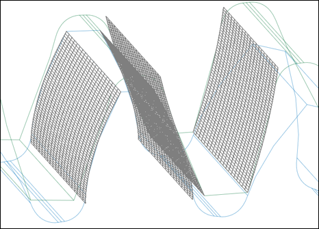
Figure 19.34 Contact pressure patch preview
Contact Analysis for All: If this function is used, user can change contact analysis for all gear pairs though contact analysis dialog box.
Figure 19.35 Gear Contact Analysis dialog box
Meta Model for All: If this function is used, user can change gmm files for all gear pairs though meta model dialog box.
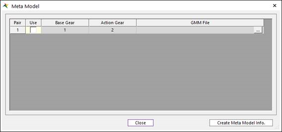
Figure 19.36 Gear Meta Model dialog box
Settings for All: If this function is used, user can change settings for all gear pairs though settings dialog box.
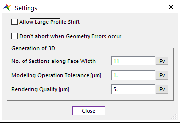
Figure 19.37 Settings dialog box
Create Gear Pairs for Planetary Gear: If this function is used, user can easily create a planetary gear group though single pinion planetary gear dialog box. Before using this function, elements that make up the planetatry gear, sun gear, planet gear, and internal gear must be predefined in the Gear Geometry section. When this dialog box is opened, it shows the rotation angles that the planet gear can be generated. The user only has to select appropriate rotation angles among them. And, when this dialog box is closed, the Gear Pair section is automatically updated with the selected information.
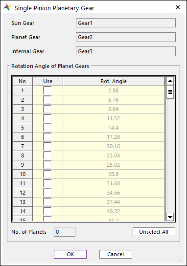
Figure 19.38 Single Pinion Planetary Gear dialog box
Note
KISSsoft Gear supports gear train with more than 1 pair. You can click Add in Gear Geometry section and Gear pair section to add gear pair. In Gear ID, 1 means the start of the gear train. So, the action gear ID cannot be 1. To define multiple gear trains, you can define multiple gear trains based on gear ID 1. And, each gear train can be created at any desired position by defining the rotation angle. For example, assuming that Gear1, Gear2, and Gear3 are defined in the Gear Geometry section, and three Gear Trains are defined in an arbitrary order, they can be defined as follows.
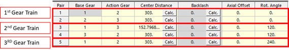
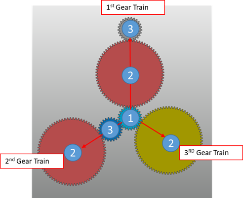
Figure 19.39 Multiple Gear Train
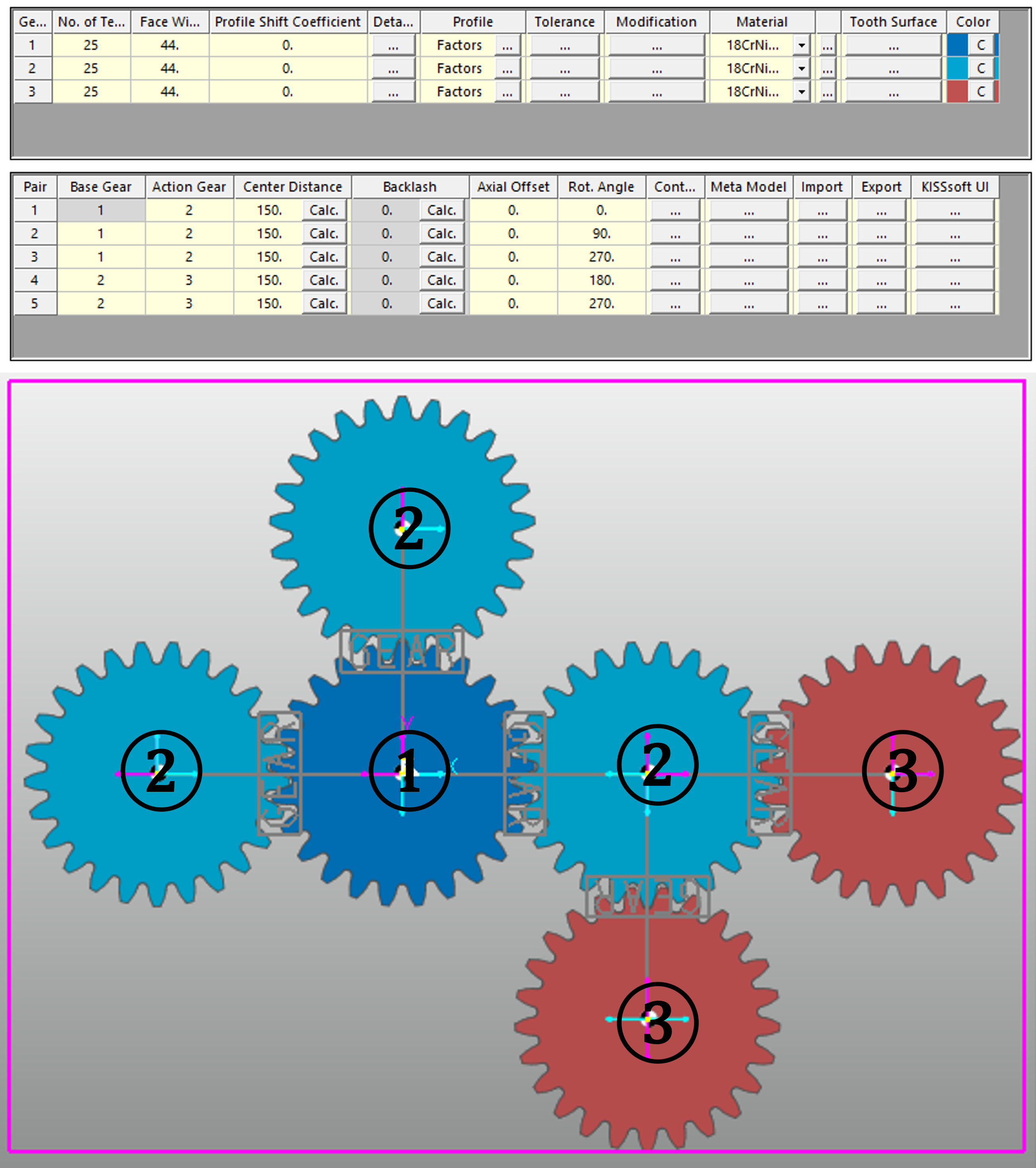
Figure 19.40 Multiple Gear Train : In case that the base gear ID of the gear pair is not 1
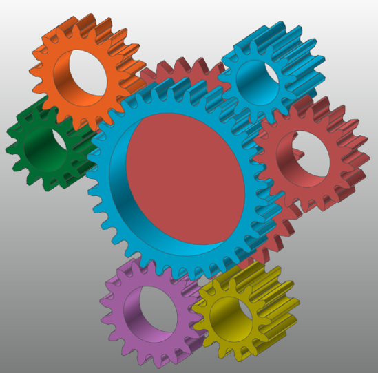
Figure 19.41 Multiple Gear Train : Spur Differential Gear
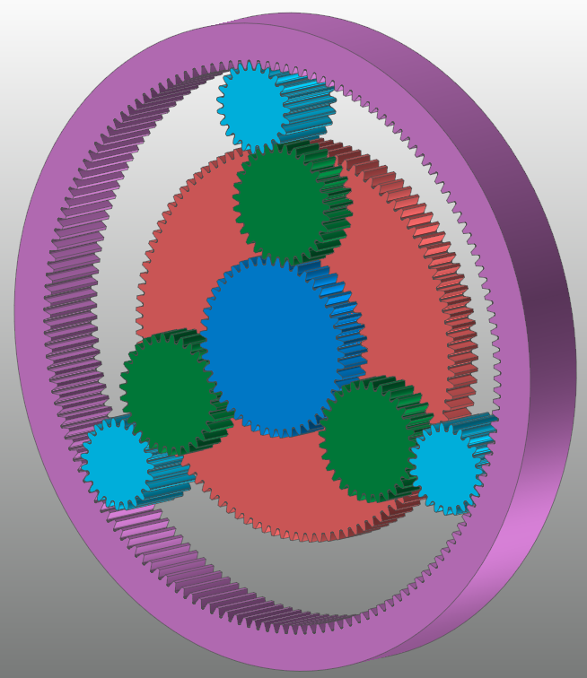
Figure 19.42 Multiple Gear Train : Ravigneaux Gear