12.3.9. Manual Mesh
RecurDyn/Mesher supports to get shell or solid elements by this function.
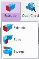
Figure 12.48 Manual Mesh functions
12.3.9.1. Extrude Manual Mesh
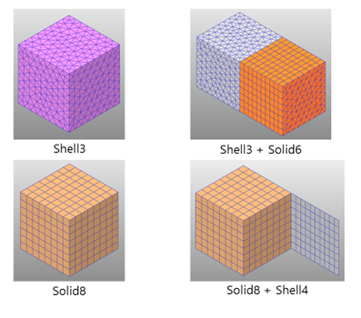
Figure 12.49 The Extrude function in Manual Mesh
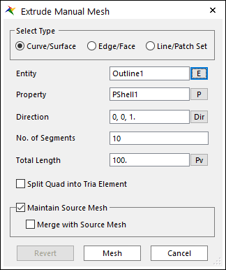
Figure 12.50 Extrude Manual Mesh dialog box
Select Type: The type of the source entity to extrude.
Curve/Surface: Select a curve or surface.
Edge/Face: Select an edge or face.
Line/Patch Set: Select a Line Set or Patch Set.
Entity: Selects the entity that matches the Select Type.
Property: Selects a proper property. Because you create solid elements from shell elements using this function, it is proper to select solid property regardless of the Type.
Direction: Defines the direction to extrude.
No. of Segments: Defines the number of segments to the total length.
Total Length: Defines the total length of meshed entity. A parametric value can be used. If the PV is modified, the manual mesh is updated.
Split Quad into Tria Element: Decides to split quad into tria elements.
Maintain Source Mesh
If it’s checked, the used source mesh exists after executing manual mesh.
If it’s unchecked, the used source mesh removed.
Merge with Source Mesh: Although the source mesh remains after the manual mesh, the result mesh does not share nodes with the source mesh. If this option is checked, the result mesh shares the nodes with the source mesh.
Revert: Returns the base meshed result.
Mesh: Executes the mesh. You can see the mesh information such as the number of nodes and elements in Message Window after finishing to mesh geometry.
12.3.9.2. Spin Manual Mesh
When using the Spin function by using a face in Manual Mesh, the several types of elements can be generated as follows. The first case is to generate the Solid8 and Solid6 elements form the Shell4 elements as shown in the Figure 12.51. And, the second case is to generate the Solid6, Solid4 and Solid5 elements from Shell3 elements as shown in the Figure 12.52. In addition, Spin function supports to create fflex body with shell and solid together like as extrude function.
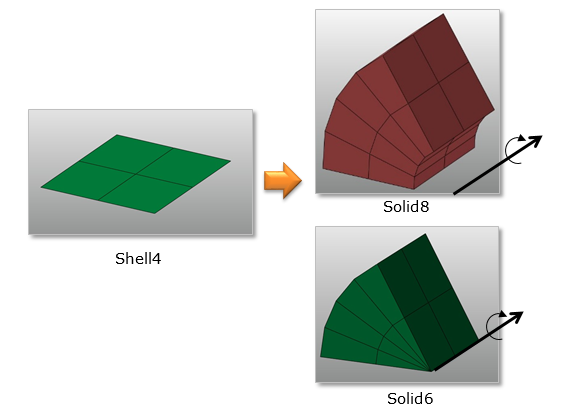
Figure 12.51 The first case to use the Spin function in Manual Mesh
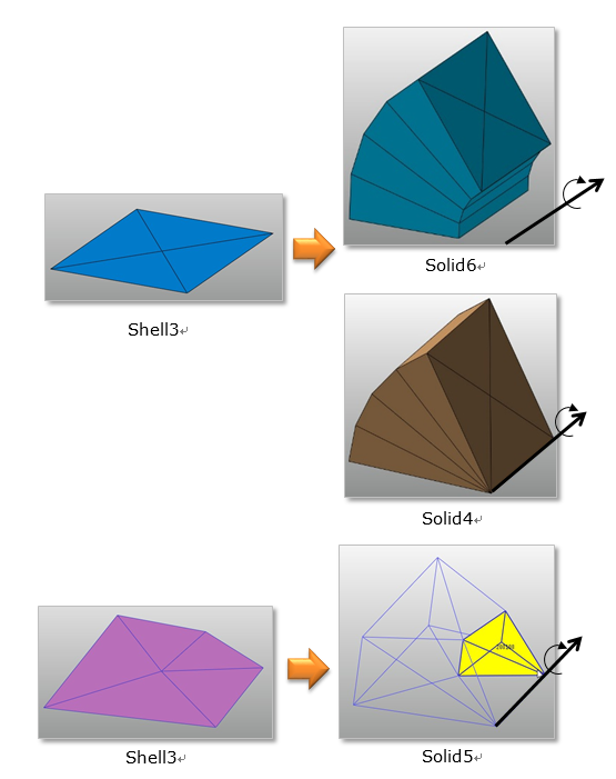
Figure 12.52 The second case to use the Spin function in Manual Mesh
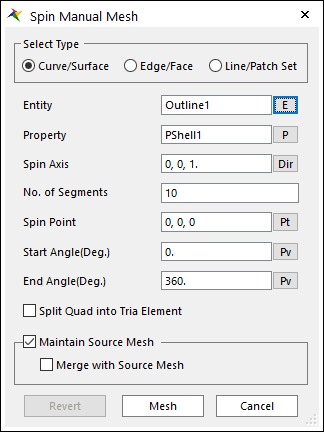
Figure 12.53 Spin Manual Mesh dialog box
Select Type: The type of the source entity to spin.
Curve/Surface: Select a curve or surface.
Edge/Face: Select an edge or face.
Line/Patch Set: Select a Line or Patch Set.
Entity: Selects the entity that matches the Select Type.
Property: Selects a proper property. Because you create solid elements from shell elements using this function, it is proper to select solid property regardless of the Type.
Spin Axis: Defines the axis to spin.
No. of Segments: Defines the number of segments from the start angle to the end angle.
Spin Point: Defines the center point of spin. A parametric point can be used. If the PV is modified, the manual mesh is updated.
Start Angle(Deg.): Defines the start angle of spin. A parametric point can be used. If the PV is modified, the manual mesh is updated.
End Angle(Deg.): Defines the end angle of spin. A parametric point can be used. If the PV is modified, the manual mesh is updated.
Split Quad into Tria Element: Decides to split quad into tria elements.
Maintain Source Mesh
If it’s checked, the used source mesh exists after executing manual mesh.
If it’s unchecked, the used source mesh removed.
Merge with Source Mesh: Although the source mesh remains after the manual mesh, the result mesh does not share nodes with the source mesh. If this option is checked, the result mesh shares the nodes with the source mesh.
Revert: Returns the base meshed result.
Mesh: Executes the mesh. You can see the mesh information such as the number of nodes and elements in Message Window after finishing to mesh geometry.
12.3.9.3. Sweep Manual Mesh
Sweep Mesh create solid elements from shell elements along the curve. Shell elements sweep along the curve.
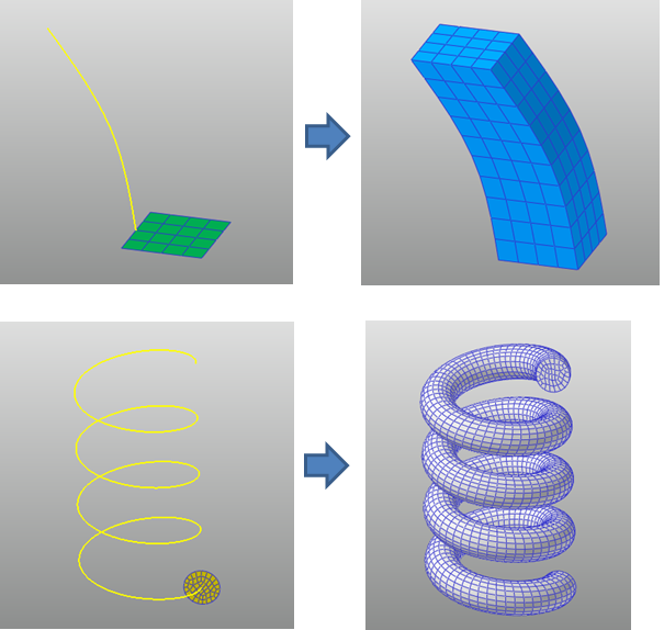
Figure 12.54 The case to use the Sweep function in Manual Mesh
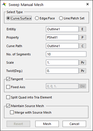
Figure 12.55 Sweep Manual Mesh dialog box
Select Type: The type of the source entity to sweep.
Curve/Surface: The result mesh of the curve and surface geometry is swept.
Edge/Face: The part of the result mesh at the position of the edge or face is swept.
Line/Patch Set: The mesh that belong to the line set or patch set is swept.
Entity: Selects the entity that matches the Select Type.
Property: Selects a proper property. Because you create solid elements from shell elements using this function, it is proper to select solid property regardless of the type.
Curve Path: Select a curve (wire body) to sweep along.
No. of Segments: Defines the number of segments to the total length of the curve.
Scale: When sweep the mesh, the node positions from the curve are adjusted by the scale value. A parametric value can be used. If the PV is modified, the manual mesh is updated.
Twist(Deg.): When sweep the mesh, the node positions are rotated around the tangent axis of the curve. A parametric value can be used. If the PV is modified, the manual mesh is updated.
Tangent: If it’s checked, sweep mesh considers the tangent of the curve.
Fixed Axis: When using tangent option, if it’s checked, the rotation around the specified axis is ignored.
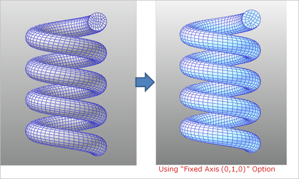
Figure 12.56 Example of Sweep Manual Mesh using the Fixed Axis option
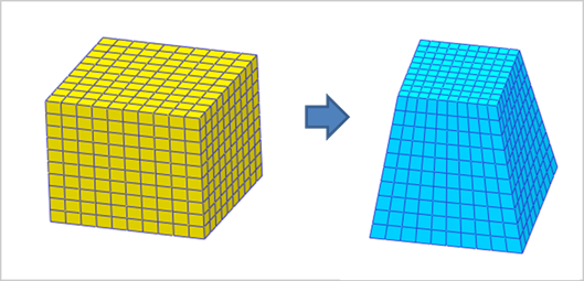
Figure 12.57 Example of Sweep Manual Mesh using the Scale option
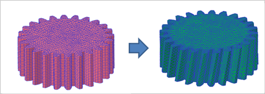
Figure 12.58 Example of Sweep Manual Mesh using the Twist option
Split Quad into Tria Element: Decides to split quad into tria elements.
Maintain Source Mesh
If it’s checked, the used source mesh exists after executing manual mesh.
If it’s unchecked, the used source mesh removed.
Merge with Source Mesh: Although the source mesh remains after the manual mesh, the result mesh does not share nodes with the source mesh. If this option is checked, the result mesh shares the nodes with the source mesh.
Revert: Returns the base meshed result.
Mesh: Executes the mesh. You can see the mesh information such as the number of nodes and elements in Message Window after finishing to mesh geometry.