25.12.3. Distance Sensor
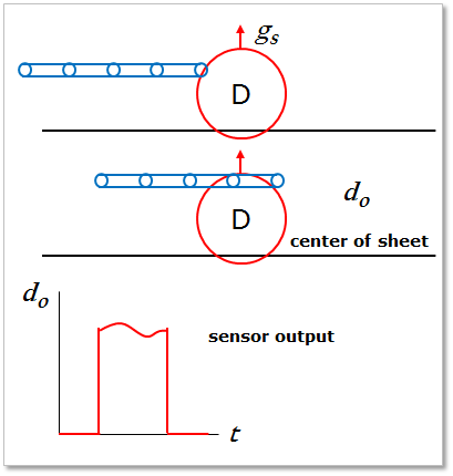
Figure 25.98 Distance Sensor
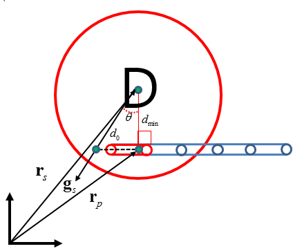
Figure 25.99 Definition of Output Value of Distance Sensor
First, the sensor finds the closest point of sheet from the sensor center position. And a position of sheet is checked whether the position is in the range of sensor. If the position is in the sensor, the distance from sensor center to sheet on sensing direction is computed. As shown in Figure 25.99, if a sheet body passes to the range of the sensor, the sensor output can be computed from the following equation.
\({{d}_{\min }}=\left| {{\mathbf{r}}_{s}}-\ {{\mathbf{r}}_{p}} \right|\)
\(\theta ={{\cos }^{-1}}({{\mathbf{g}}_{s}}\cdot \tfrac{{{\mathbf{r}}_{s}}-{{\mathbf{r}}_{p}}}{\left| {{\mathbf{r}}_{s}}-{{\mathbf{r}}_{p}} \right|})\)
\({{d}_{0}}=\frac{{{d}_{\min }}}{\cos \theta}\)
- where,
- \({{d}_{o}}\): the result of sensor. (Output Value)\({{\mathbf{r}}_{p}}\): the position of the closest point of sheet body on the direction and in the range of the sensor.\({{\mathbf{r}}_{s}}\): the position of sensor center.\({{\mathbf{g}}_{s}}\): the specified direction of the sensor.\({{d}_{\min }}\): the minimum distance from sensor center to mid plane of sheet.
Note
25.12.3.1. Modeling Options
The user can create a distance sensor as follows.
Point, Direction, Distance
Point: Selects a point on a body to define the center of distance sensor.
Direction: Defines a direction of distance sensor.
Distance: Defines a range of region to measure output.
Body, Point, Direction, Distance
Body: Selects a body to define the parent body of distance sensor.
Point: Selects a point on a body to define the center of distance sensor.
Direction: Defines a direction of distance sensor.
Distance: Defines a range of region to measure output.
25.12.3.2. Properties
The user can modify properties for the distance sensor such as a position, sensing target entity, and direction using Distance Sensor property page.
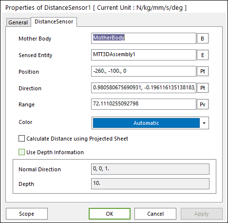
Figure 25.100 Distance Sensor property page
Mother Body: Defines the body on which the Distance Sensor is fixed.
Sensed Entity: Defines the sensed entity by the Distance Sensor of MTT3D.
If MTT3DAssembly is set, all sheets defined in the assembly become a sensing target.
If a sheet body is set, only the sheet becomes a sensing target.
Position: Defines the center point of Distance Sensor. The user can input this value as the Parametric Point.
Direction: Defines the direction of Distance Sensor. The user can input this value as the Parametric Point.
Range: Defines the detecting range of Distance Sensor. The user can input this value as the Parametric Value.
Color: Allows selecting the graphic color of Distance Sensor.
Calculate Distance of Projected Sheet: The sensor output is calculated to the distance of outer lines for the projected sheet on a normal plane of the sensor as shown in Figure 25.101.
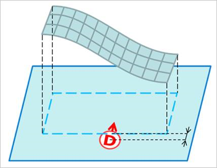
Figure 25.101 projected sheet outer line on a normal plane of sensor
Use Depth Information: Defines the sensing region by using the Normal Direction and Depth. The shape of sensing region is the cylinder type defined by the end point (Position), the radius (Range), the length (Depth), the lengthwise direction (Normal Direction) as shown in Figure 25.102.
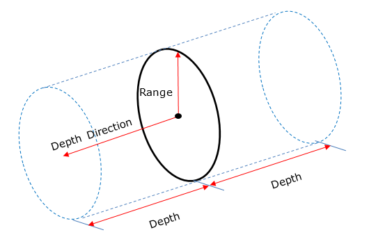
Figure 25.102 sensing region when the Use Depth Information is checked
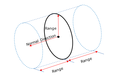
Figure 25.103 sensing region when the Use Depth Information is unchecked