9.7.4.1. Linear elastic
The linear material is classified in isotropic or orthotropic.
The stress/strain matrix is constant.
9.7.4.1.1. Isotropic
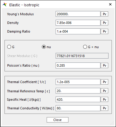
Figure 9.57 Elastic – Isotropic(Linear) dialog box
Young’s Modulus, Density, and Damping Ratio are set.
Young’s Modulus [ \(Force/Length^2\) ]: Defines the Young’s modulus of the isotropic.
Damping Ratio
MFBD system equation is composed of mass matrix, damping matrix and stiffness matrix. Generally, mass matrix and stiffness matrix can be evaluated using finite element formulation, but damping matrix cannot be evaluated using it. So, damping ratio, which is a ratio between stiffness matrix and damping matrix, is used to evaluate damping matrix.
\(\mathbf{C}=\zeta \,\mathbf{K}\)
where: | \(\mathbf{C}\): Damping Matrix | \(\mathbf{K}\): Stiffness Matrix | \(\zeta\): Damping Ratio
Note
The Damping Ratio does not mean an actual damping divided by a critical damping. The Damping Ratio is related the Rayleigh Damping of the structural dynamics. The Rayleigh Damping means that the damping matrix is defined a linear combination of Mass and Stiffness matrices as following equation.
\(\mathbf{C}=\alpha \mathbf{M}+\beta \mathbf{K}\)
\(\alpha\) (a proportional coefficient of Mass matrix) is always set zero, and \(\beta\) (a proportional coefficient of Stiffness matrix) is related the Damping Ratio for the RecurDyn/FFlex.
In general, Shear Modulus is calculated from Young’s Modulus and Poisson’s Ratio in the isotropic material.
Using this relation, Shear Modulus (\(G\)) and Poisson’s Ratio (\(\nu\)) are set from the follow options. \(G\), \(\nu\), and the \(G+\nu\).
\(G\) [ \(Force/Length^2\) ]
If Shear Modulus (\(G\)) is set, Poisson’s Ratio (\(\nu\)) is calculated.
If the values of Poisson’s Ratio are not in the range of 0 to 1, then the warning message is seen for the wrong material property.
\(\nu\)
If Poisson’s Ratio is set, then the Shear Modulus(\(G\)) is calculated.
\(G\) + \(\nu\)
The values of Shear Modulus (\(G\)) and Poisson’s Ratio (\(\nu\)) are set.
But If the relation of Shear Modulus (\(G\)), Poisson’s Ratio (\(\nu\)), and Young’s Modulus is not met, the warning message is seen for the wrong material property.
Thermal Coefficient: The ratio between the original length and stretched length by the temperature. It is the material property. The default is set to 1.2e-5 which is similar to the Steel. The value should be set between 0.0 and 1.0e-3. If the value is set to 1.2e-5 then the temperature 1 degree changing makes 1.2e-5 thermal strain is considered. The negative or higher than 1.0e-3 cannot be used.
Thermal Reference Temp [ \(^{\circ}C\) ]: The reference temperature is user-defined value. The difference between current temperature and reference temperature occurs the thermal deformation.
Stress-strain matrix ( \(E\) )
\(\begin{aligned} & {{E}^{-1}}\,=\,\left[ \begin{matrix} \frac{1}{E} & \frac{-\nu }{E} & 0 \\ \frac{-\nu }{E} & \frac{1}{E} & 0 \\ 0 & 0 & \frac{1}{G} \\ \end{matrix} \right] \\ & \\ \end{aligned}\)
Specific Heat (\(J/kg^{\circ}C\) ]: The specific heat capacity of a substance is the heat capacity of a sample of the substance divided by the mass of the sample. This value is used for making capacity matrix for conduction analysis.
Thermal Conductivity (\(W/m \cdot ^{\circ}\! C\) ]: The thermal conductivity of a material is a measure of its ability to conduct heat. This value is used for making conductivity matrix for conduction analysis.
9.7.4.1.2. Orthotropic2D
The orthotropic material is applied to shell4.
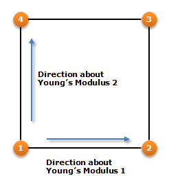
\(E1\) is the direction of local node 1 and 2.
\(E2\) is the vertical direction of \(E1\).
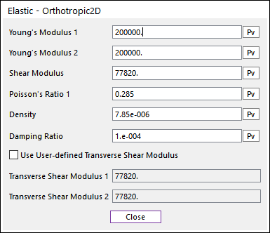
Figure 9.58 Elastic - Orthotropic2D dialog box
Young’s Modulus 1 ( \(E1\) ) [ \(Force/Length^2\) ]: Defines the Young’s modulus of the orthotropic in local direction by local node 2 to local node 1.
Young’s Modulus 2 ( \(E2\) ) [ \(Force/Length^2\) ]: Defines the Young’s modulus of the orthotropic in local direction by local node 4 to local node 1.
Shear Modulus ( \(G\) ) [ \(Force/Length^2\) ]: Defines the in-plane shear modulus.
Poisson’s Ratio 1 ( \({{\nu }_{1}}\) ): Defines the passions ratio. Note that.
\({{\nu }_{1}}{{E}_{2}}={{\nu }_{2}}{{E}_{1}}\)
Damping Ratio ( \(\xi\) ): Defines the damping ratio. The structural damping ratio of element and the damping matrix of is C computed from the following equation.
\(\mathbf{C}=\zeta \,\mathbf{K}\)
where:
\(\mathbf{C}\): Damping Matrix\(\mathbf{K}\): Stiffness Matrix\(\zeta\): Damping RatioUse User-defined Transverse Shear Modulus: Defines the transverse shear modulus. If this check option is disabled, shear correction factor is used to obtain the transverse shear modulus, which is a default value for original orthotropic material. If checked, user can set the transverse shear modulus.
Transverse Shear Modulus 1 [ \(Force/Length^2\) ]: Transverse shear modulus in direction 1 (\(G1z\)).
Transverse Shear Modulus 2 [ \(Force/Length^2\) ]: Transverse shear modulus in direction 2 (\(G2z\)).
Stress-strain matrix ( \(E\) )
\({{\mathbf{E}}^{-1}}=\left[ \begin{matrix} \frac{1}{{{E}_{1}}} & \frac{-{{\nu }_{2}}}{{{E}_{2}}} & 0 & 0 & 0 \\ \frac{-{{\nu }_{1}}}{{{E}_{1}}} & \frac{1}{{{E}_{2}}} & 0 & 0 & 0 \\ 0 & 0 & \frac{1}{G} & 0 & 0 \\ 0 & 0 & 0 & \frac{1}{kG} & 0 \\ 0 & 0 & 0 & 0 & \frac{1}{kG} \\ \end{matrix} \right],\,\,\,\,k=\cfrac{5}{6}\)
Stress-strain matrix (E) with user-defined transverse shear modulus
\({{\mathbf{E}}^{-1}}=\left[ \begin{matrix} \frac{1}{{{E}_{1}}} & \frac{-{{\nu }_{2}}}{{{E}_{2}}} & 0 & 0 & 0 \\ \frac{-{{\nu }_{1}}}{{{E}_{1}}} & \frac{1}{{{E}_{2}}} & 0 & 0 & 0 \\ 0 & 0 & \frac{1}{G} & 0 & 0 \\ 0 & 0 & 0 & \frac{1}{{{G}_{1Z}}} & 0 \\ 0 & 0 & 0 & 0 & \frac{1}{{{G}_{2Z}}} \\ \end{matrix} \right]\)
9.7.4.1.3. Anisotropic2D
The anisotropic material is applied to shell4.
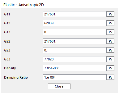
Figure 9.59 Elastic - Anisotropic2D dialog box
Direction 1 is toward from local node 1 to node 2.
Direction 2 is vertical direction of Direction 1.
\(G11\) to \(G33\) represents the component of constitutive matrix in shell material.
Damping Ratio ( \(\xi\) ): Defines the damping ratio. The structural damping ratio of element and the damping matrix of is C computed from the following equation.
\(\mathbf{C}=\zeta \,\mathbf{K}\)
where:
\(\mathbf{C}\) : Damping Matrix\(\mathbf{K}\) : Stiffness Matrix\(\zeta\) : Damping RatioStress-strain matrix ( \(E\) )
\(\mathbf{E}=\left[ \begin{matrix} {{G}_{11}} & {{G}_{12}} & {{G}_{13}} & 0 & 0 \\ {{G}_{12}} & {{G}_{22}} & {{G}_{23}} & 0 & 0 \\ {{G}_{13}} & {{G}_{23}} & {{G}_{33}} & 0 & 0 \\ 0 & 0 & 0 & {{G}_{22}} & {{G}_{23}} \\ 0 & 0 & 0 & {{G}_{23}} & {{G}_{33}} \\ \end{matrix} \right]\)