6.4.4.3. Cam 2D
A Cam2D Contact generates a force between a circle (or a sphere) and a curve. This contact is smooth circle to curve contact in 2D. The base curve has a RM and many points. The action circle has a RM and its radius. The base curve is parameterized from many points and creates a contact curve fitted on a cubic spline.
The circle and the curve must belong to two different bodies.
If the base curve is not only convex curve but also concave curve, the generalized contact force is very smooth. There is no noise caused by a contact geometry approximation.
This contact supports only one contact point at a point where a contact penetration is the deepest.
The contact force can be not only linear or exponential but also nonlinear spline characteristics to the contact penetration and its velocity.
The base curve is a curve fitted to passing points as shown in Figure 6.391.
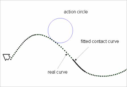
Figure 6.391 Fitted base contact curve
As shown Figure 6.392, let’s suppose a roller pair in 2D. The left and right roller pairs are the same material property. The contact of left roller pair is modeled with Cam2D Contact and that of right roller pair is modeled with a circle to curve contact. The resultant contact forces are compared in Figure 6.393. As shown in Figure 6.393, the contact force generated by the Cam2D is very smooth. On the other hand, the solutions of the circle to curve contact are noisy. But as the number of segments of a base curve is larger, the contact force is closer to that of Cam2D.
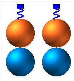
Figure 6.392 Example model of Cam2D Contact
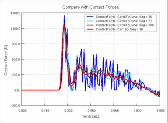
Figure 6.393 Comparison with the solutions
6.4.4.3.1. Modeling Options
In the case of Cam2D contact, circle and sphere geometry types are supported for an action geometry and a curve geometry type is supported for a base geometry when creating.
Curve, Circle(Sphere)
Curve: Selects a curve to define a base curve.
Circle(Sphere): Selects a circle or a sphere to define an action circle.
Curve, MultiCircle(Sphere)
Curve: Selects a curve to define a base curve.
MultiCircle(Sphere): Selects some circles or spheres to define action circles.
Curve, Circle(Sphere), Curve, Circle(Sphere)
Curve: Selects a curve to define a base curve.
Circle(Sphere): Selects a circle or a sphere to define an action circle.
Curve: Selects a curve to define another base curve.
Circle(Sphere): Selects a circle or a sphere to define another action circle.
MultiCurve, MultiCircle(Sphere)
MultiCurve: Selects some curves to define base curves.
MultiCircle(Sphere): Selects some circles or spheres to define action circles.
6.4.4.3.2. Properties
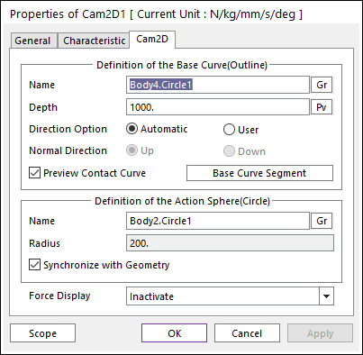
Figure 6.394 Properties of Cam2D dialog box
Definition of The Base Curve (Outline)
Entity Name: Defines the name of base curve or outline. The base curve or outline can be dispatched from the Working Window by clicking Gr.
Depth: Defines the depth of contact face of the base curve. The user can change the depth as the parametric value by clicking PV.
Normal Direction: Defines the normal direction of base curve or outline for a contact.
The contact is available in the specified direction.
As selecting Up or Down, the user can change the contact direction of a base geometry.
If this page is activated, the normal direction is automatically shown on the Working Window.
Preview Contact Curve: If this option is checked, the points making the contact curves are shown on the Working Window.
Base Curve Segment: Accesses Base Curve Segment dialog box. For more information, click here.
Definition of The Action Sphere(Circle)
Entity Name: Defines the name of action sphere or circle. The user can change the action sphere by using the navigation method.
Radius: Shows the radius of action sphere or circle. This value is automatically determined by the radius of the action geometry but if the user doesn’t check the Synchronize with Geometry option, the user can directly input the radius or change it as the parametric value by clicking PV.
Synchronize with Geometry
If this option is checked, Radius in contact properties is automatically defined with that of the specified graphic. (The default is checked)
If this option is not checked, the user can modify the contact properties.
Force Display: Graphically displays the resultant force vector on the view window.