33.3.1.3. Constraint Bearing
A constraint bearing is defined between two bodies. The created position types are two:
Connecting Rod & Piston Pin (CR_PP)
Piston Pin & PisTon(PP_PT)
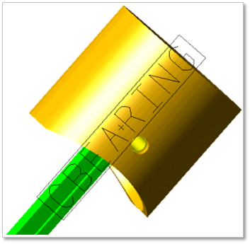
Figure 33.49 Constraint bearing
33.3.1.3.1. Modeling Options
Click the Constraint icon of the Connector group in the Piston tab. The user can see the Crank Component Bearing –Constraint Bearing dialog box.
The user can choose the following types in Component Type and select the position where the constraint bearing is created in Component Index.
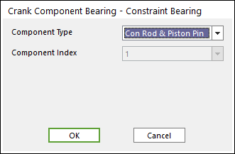
Figure 33.50 Crank Component Bearing – Constraint Bearing dialog box
Click OK
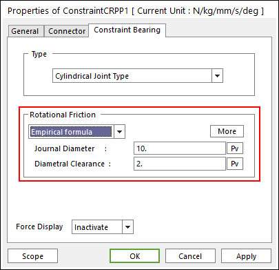
33.3.1.3.2. Properties
Click the right mouse button on the constraint bearing component to choose Properties of the constraint bearing. The user can modify the property of Constraint Bearing dialog box.
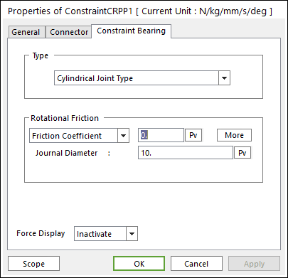
Figure 33.51 Constraint Bearing property page
Type: Spherical Joint, Cylindrical Joint and Revolute Joint Type.
The user can refer the following table for each constraint bearing.
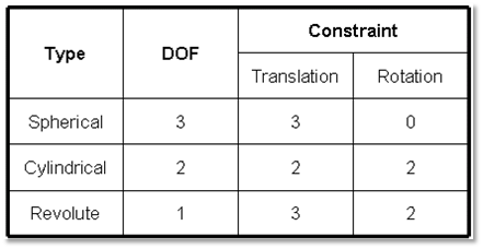
Table 1 Constraint bearing characteristics
Please refer to the Friction type in below.
Standard Friction
Select Friction Coefficient in the combo box.
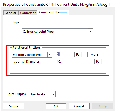
Figure 33.52 Coulomb Friction
Click More and then enter values to define Coulomb friction. For more information, click here.
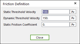
Figure 33.53 Coulomb Friction dialog box
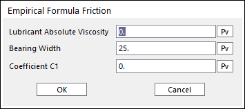
Empirical Formula