29.3.1. Modeling Options
Click the Assembly icon of the Assembly group in the Belt tab.
Select a set of bodies with the belt system making contacts. Whenever you move the mouse, the underling body is highlighted and you can see the solid line connecting the previously selected body and highlighted body. After making a closed loop, the following dialog box for the assembling belt system appears.
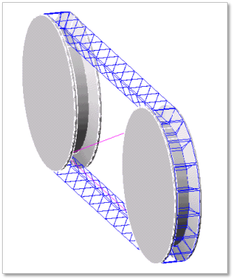
Figure 29.55 Assembly Belt System
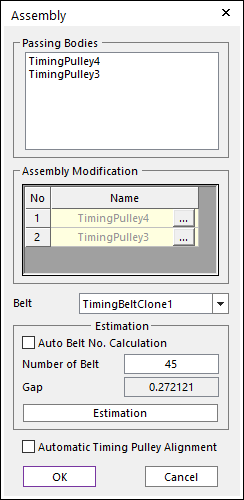
Figure 29.56 Assembly dialog box
Enter the number of belt segments and click Estimation. You can compute approximately pre-tension between belt segments from an estimated belt gap.
If Automatic Timing Pulley Alignment option is checked, the timing pulley is rotated to match the position of the belt segments.
Click OK, then the Belt assembly is completed.
29.3.1.1. Assembly dialog box
During assembly, a below dialog box is shown.
Figure 29.57 Assembly dialog box
Passing Bodies: Shows the list of assembled bodies.
Assembly Modification: Modifies the assembly information about Timing Pulley. For more information, click here.
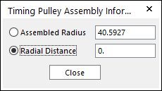
Figure 29.58 Timing Pulley Assembly Information dialog box
Belt: Selects a clone link.
Estimation: The user can estimate the assembled belts.
Auto Belt No. Calculation: If the user clicks Estimation with the checked this option, the number of belts is set automatically.
Number of Belt: Modifies the number of belts.
Gap: Shows a value of gap.
Automatic Timing Pulley Alignment
If this option is check, after checking the interference between timing pulley and timing belts. The timing pulley geometries are rotated and adjusted not to interference with the timing belts.