24.4.2. Movable Roller
The movable roller is linked to a rotational axis retainer (RAR) with a revolute joint. The retainer is linked to ground with a translational joint.
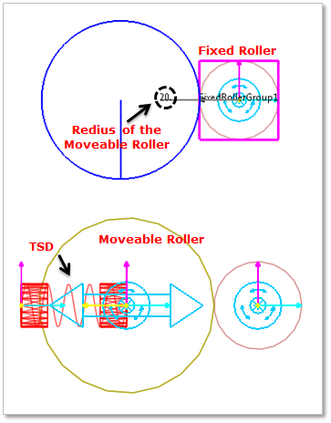
Figure 24.34 Movable roller
24.4.2.1. Modeling Options
The user can create the movable roller group as follows.
Fixed Roller Group, Direction, Radius
Fixed Roller Group: Selects a fixed roller group.
Direction: Defines the position of the movable roller group with respect to the fixed roller group.
Radius: Defines a radius of the movable roller group.
Fixed Roller Group, Direction, Radius, Distance
Fixed Roller Group: Selects a fixed roller group.
Direction: Defines the position of the movable roller group with respect to the fixed roller group.
Radius: Defines a radius of the movable roller group.
Distance: Defines an initial gap between the fixed roller group and the movable roller group.
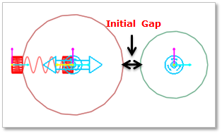
Figure 24.35 Initial gap of Movable Roller
24.4.2.2. Properties
The user can modify the properties of movable roller in this dialog box.
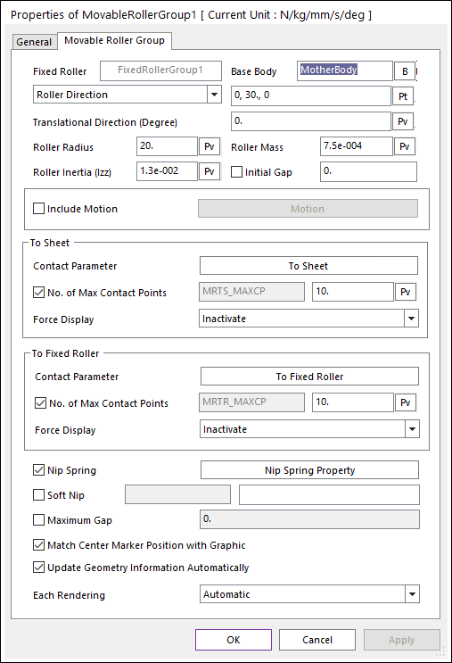
Figure 24.36 Movable Roller property page
Fixed Roller: Displays the name of the fixed roller
Base Body: Defines the base body of translational joint.
Roller Direction: Defines the position of movable roller with respect to fixed roller. The user can use input this value as Parametric Point.
Roller Angle (PV:R): Defines the angle position of movable roller with respect to fixed roller. The angle unit is radian in case of using Parametric Value.
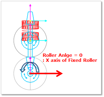
Figure 24.37 Definition of Roller Angle
Translational Direction (Degree): Defines the translation direction. Default is 0.0 degree. The input angle range is from -90.0 to 90.0 degree. (Translation Direction effects the Soft Nip function. The moving direction of the Dummy body for the Soft Nip is the same with the Translation Direction. But, in the case of Maximum Gap, and Initial Gap functions are not related with this Translational Direction.)
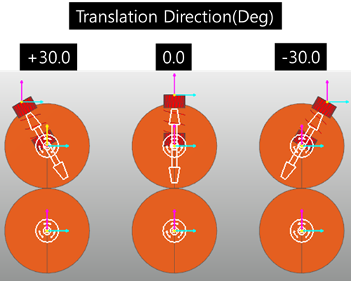
Figure 24.38 Effect of the Translation Direction
Roller Radius: Defines the radius of movable roller.
Roller Mass: Defines the mass of movable roller.
Roller Inertia (Izz): Defines the mass moment of inertia with respect to the z-axis of the center marker of the roller.
Initial Gap: Defines the initial gap between the fixed roller and the movable roller.
Include Motion: Defines the angular motion of movable roller. The user can define the roller displacement, velocity and acceleration by using Expression. Refer to Motion.
Contact Parameter: Allows the user to modify contact parameters by clicking To Sheet and To Fixed Roller.
To Sheet: In this dialog box, the user can modify the contact parameters of contact forces applied between the sheet and the fixed roller. Refer to Contact formulas for MTT2D.
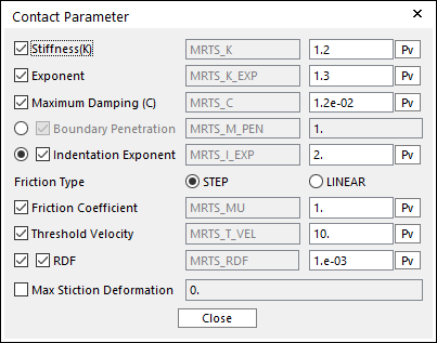
Figure 24.39 Contact Parameter dialog box
To Fixed Roller: In this dialog box, the user can modify the contact parameters of contact forces applied between the movable roller and the fixed roller. Refer to Contact formulas for MTT2D.
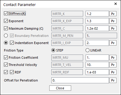
Figure 24.40 Contact Parameter dialog box
No. of Max Contact Points (“To Sheet” and “To Fixed Roller”): Defines the number of max contact point for output. User can define this value from 1 to 5000. This value only affects Force Display and RPLT data about the contact points. The default value is 10.
Force Display (“To Sheet” and “To Fixed Roller”): Graphically displays the all contact force vectors (the sum of the normal and tangential contact force) at each contact point up to the No. of Max Contact Point.
Nip Spring: If the user checks the check box, then the spring is activated on the movable roller. The user can modify Nip spring property by clicking Nip Spring Property.
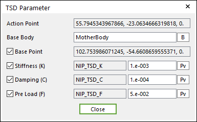
Figure 24.41 TSD Parameter dialog box
Soft NIP: Defines the motion of translational joint of dummy body using Expression. (Refer to Soft Nip)
Maximum Gap: Defines the maximum gap between Movable Roller and Fixed Roller.
Match Center Marker Position with Graphic: If this is checked, the position of center marker of Movable Roller body always matches with the center of roller geometry.
Each Rendering: The selected mode can be displayed in Each Render mode.