32.2.6. FlyWheel
A flywheel is composed of a single body. It is attached on the end of crankshaft.
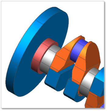
Figure 32.76 Flywheel
Terminology
Reference Parametric Marker
Width
Diameter
32.2.6.1. Modeling Options
Click the FlyWheel icon of the Crank group in the Crank tab. The user can see the Crank Component – FlyWheel dialog box.
The user can select the position where the flywheel is created in Component Index.
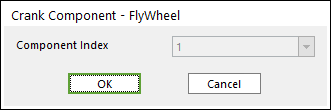
Figure 32.77 Crank Component – FlyWheel dialog box
Click OK.
32.2.6.2. Properties
Click the right mouse button on the flywheel body to choose Properties of flywheel. The user can modify the property of flywheel in the following dialog.
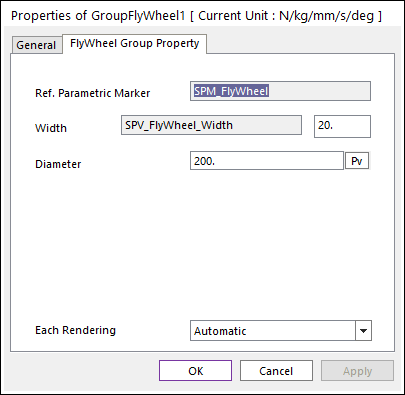
Figure 32.78 GroupFlywheel property page
Reference Parametric Marker: Controls the position of flywheel. It is also special parametric marker.
Width and Diameter: Are independent values, which are not related with other entities. Refer to a following Figure 32.79.
Each Rendering: The selected mode can be displayed in Each Render mode.
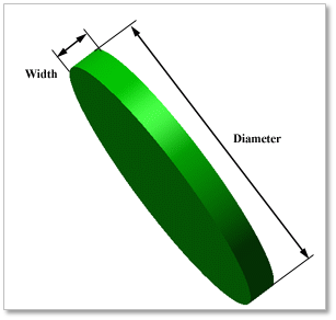
Figure 32.79 Geometrical information of Flywheel
Connection Information of Fly Wheel

Figure 32.80 Connection Information
Fly Wheel & Shaft Main After are connected by Fixed Joint.
Initial Velocity
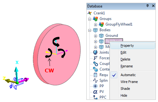
Figure 32.81 Initial velocity on Fly Wheel
In Pre-Global Data, the direction of rotation (CW / CCW) is decided. If the user selects the direction of rotation such as CW, the initial velocity is also applied to Fly Wheel as CW direction. The user can confirm the initial velocity in the properties of Fly Wheel body. To check the initial velocity, click a right mouse button on Data Base of Fly Wheel body. And then enter the properties of Fly Wheel body. The properties page is as follow.
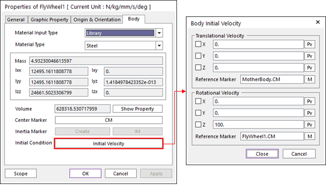
Figure 32.82 The properties of Fly Wheel body