26.8.3. Slip Sensor
This sensor allows the user to measure the difference between the velocity of the Roller and assembly (web). The beam element is that passes between the center position of the Sensor and Roller.
The direction of the sensor is the tangential direction of the center position of the sensor and the center position of the Roller.
The position of the element center of a sensing belt is to be a sensing point.
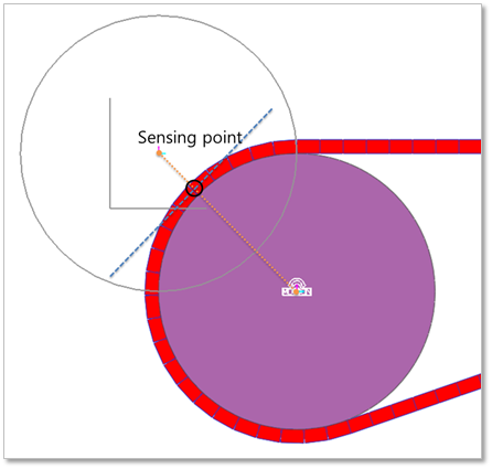
Figure 26.46 Sensing point of the beam element.
The sensor output can be computed from the following equation.
\(V_p\) = [the rotational velocity of roller] * [the distance between the center of roller and the center line of the beam assembly]
\(V_b\) = [the velocity of the center line of the beam assembly for the tangential direction of the radius of roller]
Reference Frame (\(A_{ref}\) = [f, g, h])
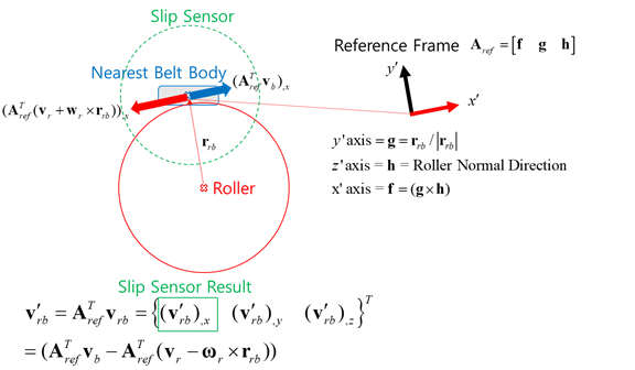
Figure 26.47 Reference Frame of the Slip Sensor
Result_Slip_Sensor = \({{\mathbf{f}}^{T}}({{\mathbf{V}}_{b}}-{{\mathbf{V}}_{p}})\)
26.8.3.1. Modeling Options
The user can create a slip sensor as follows.
RollerBody, Point, Distance
RollerBody: Selects a roller.
Point: Selects a point on a body to define the center of slip sensor.
Distance: Defines a range of region to measure output.
Note: The user should define the sensing target entity by using Slip Sensor property page.
Body, RollerBody, Point, Distance
Body: Selects a body to define the parent body of slip sensor.
RollerBody: Selects a roller.
Point: Selects a point on a body to define the center of slip sensor.
Distance: Defines a range of region to measure output.
Note: The user should define the sensing target entity by using Slip Sensor property page.
RollerBody, Assembled Body, Point, Distance
RollerBody: Selects a roller.
Assembled Body: Selects a beam assembly as a target entity.
Point: Selects a point on a body to define the center of slip sensor.
Distance: Defines a range of region to measure output.
Body, RollerBody, Assembled Body, Point, Distance
Body: Selects a body to define the parent body of slip sensor.
RollerBody: Selects a roller.
Assembled Body: Selects a beam assembly as a target entity.
Point: Selects a point on a body to define the center of slip sensor.
Distance: Defines a range of region to measure output.
26.8.3.2. Properties
The user can modify properties for the slip sensor such as a position, sensing target entity, and direction using Slip Sensor property page.
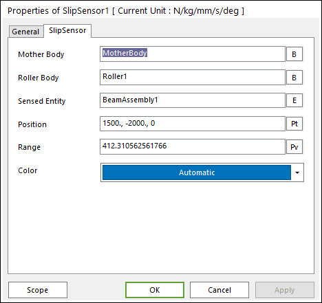
Figure 26.48 Slip Sensor property page
Mother Body: Selects the mother body of slip sensor.
Roller Body: Selects a roller as a sensing target entity.
Sensed Entity: Selects an assembled body as a sensing target entity.
Position: Defines the center of slip sensor.
Range: Defines the range of region to measure output.
Color: Defines the color of slip sensor.