6.2.4.5. Gear
A gear can be used to relate the relative coordinates of two revolute joints. The user can define the gear ratio by attaching a common velocity marker on the carrier body to which the joints are attached. The z-axis of the common velocity marker is defined by clicking two points [Point and Direction]. Therefore, the user must define the base markers of two revolute joints and the common velocity marker on the same carrier body. The z-axis of the common velocity marker becomes the tangential velocity direction of the two action bodies of revolute joints.
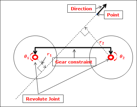
Figure 6.238 Configuration of Gear Joint
The formula for the gear constraint is
\({{\theta }_{1}}\times {{r}_{1}}+{{\theta }_{2}}\times {{r}_{2}}=0\)
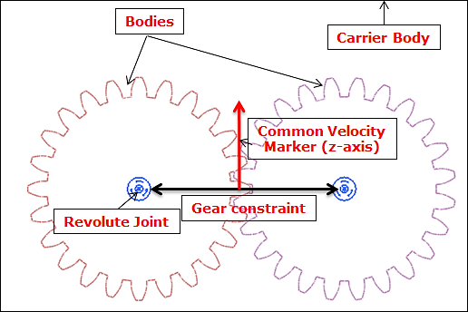
Figure 6.239 Formula for Gear Joint
A gear joint is different from a coupler as follows.
A gear joint can define two revolute joints only.
The base body of two revolute joints must be the same.
A point is defined instead of a scale.
6.2.4.5.1. Modeling Options
The user can create a joint entity as follows.
Joint, Joint, Point, Direction
Joint: Selects a joint as the first joint.
Joint: Selects a joint as the second joint.
Point: Selects a point as a position of the common velocity marker.
Direction: Defines the z-axis of the common velocity marker.
6.2.4.5.2. Properties
The user can modify the joint properties using the Joint page.
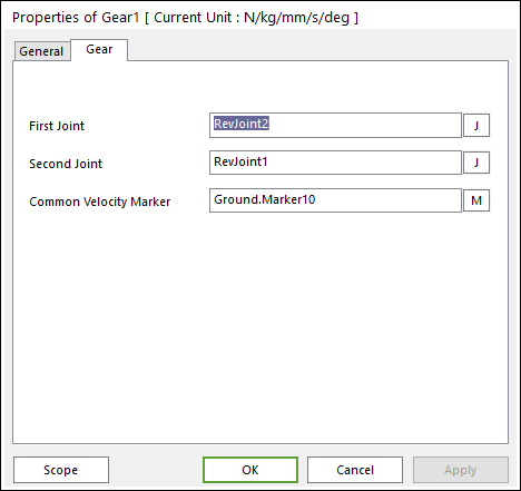
Figure 6.240 Gear property page [Joint page]
First Joint: Defines the first joint.
Second Joint: Defines the second joint.
Common Velocity Marker: Defines the common velocity marker.
Force Display: Displays the resultant force vector graphically on Working Window.