24.4. Roller Group
Roller and Sheet Interactions
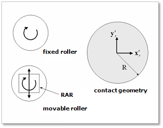
Figure 24.26 Definition of rollers
There are two types of rollers.
One is a fixed roller with one rotational degree of freedom.
The fixed roller is linked to the ground with a revolute joint.
The other is a movable roller that has two degrees of freedom for both translational and rotational motion.
The movable roller is linked to a rotational axis retainer (RAR) with a revolute joint.
The retainer is linked to the ground with a translational joint.
The contact geometry of rollers is described as a circle as shown in Figure 24.26.
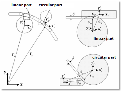
Figure 24.27 Sheet and roller interaction
The contact between a roller and a sheet has two types, as shown in Figure 24.27.
One is a roller contact to the linear part of the sheet segment.
The other is a roller contact to the circular ends of the sheet segment.
The relative displacement between a rigid segment and a roller can be computed according to the following equation.
where, \(\mathbf{r}_r\) and \(\mathbf{r}_s\) are the center position vectors of the roller and the rigid segment, respectively. The vector of \(\mathbf{d}_{sr}\) is projected by the body reference frame of a contacted rigid segment and the resultant displacement can be represented as follows.
where, \(\mathbf{A}_{s}\) is the orientation matrix of a rigid segment. From (24.14), if the absolute value of \(x\) component of \(\mathbf{d}'_{sr}\) is less than \(L_s/2\), the roller contacts the linear part of a sheet. If not, the roller is contacting the circular ends of the segment.
In a linear part contact, the contact penetration is determined as follows.
where, \(|\mathbf{d}'_{sr,y}|\) and \(\mathbf{R}_{r}\) are the \(y\) component of the vector of \(\mathbf{d}'_{sr}\) and the radius of a contacted roller, respectively. The contact positions from segment and the roller center can be computed as follows.
where, \(\mathbf{A}_r\) is the orientation matrix of a roller. The relative velocity at the contact point can be determined as follows.
where, \({\tilde{\mathbf{\omega}}}'_r\) and \({\tilde{\mathbf{\omega}}}'_s\) are angular velocities of a roller and a segment with respect to each body reference frame, respectively. The normal vector of \(\mathbf{u}_n\) and tangent vector of \(\mathbf{u}_t\) are determined as follows.
Finally, the contact normal force can be derived from (24.14), (24.15) and (24.19) and the friction force are computed from (24.17) and (24.20).
Roller and Roller Interactions
A roller to roller contact can be described as a circle-to-circle contact as shown in Figure 24.28.
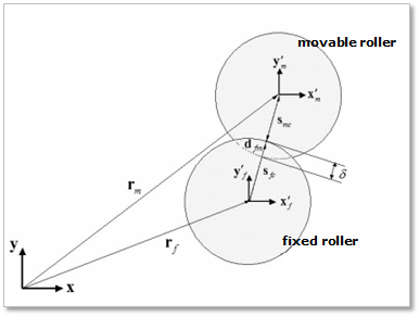
Figure 24.28 Roller and roller interactions
The relative displacement between a fixed roller and a movable roller can be computed with the following equation.
where, \(\mathbf{r}_f\) and \(\mathbf{r}_m\) are the center position vectors of the fixed roller and movable roller, respectively. The vector of \(\mathbf{d}_{fm}\) is projected by the body reference frame of the fixed roller and the resultant vector can be represented as follows.
where, \(\mathbf{A}_f\) is the orientation matrix of the fixed roller. From (24.23), the contacted penetration is determined as follows.
where, \(||{\mathbf{d}'_{fm}}||\), \(R_f\) and \(R_m\) are the distance of \({\mathbf{d}'_{fm}}\) and the radii of the rollers, respectively. The contact positions from the two roller centers can be computed as follows.
where, \({\mathbf{A}_{m}}\) is the orientation matrix of the movable roller. \({\mathbf{u}_{n}}\) contains the normal direction vectors and determined by following equation.
The positive normal direction is the same as the direction of the relative position vector between two roller center points. The tangent direction vector is determined by the right-hand rule. The relative velocity and the contact forces at the contact point can be computed similarly to the sheet and roller interactions.
Soft Nip and Maximum Gap of Movable Roller
The user can use a function expression of soft nip for adjusting the gap between two rollers. If the soft nip is activated, a dummy body that is connected to a base body by a translational joint is automatically created as shown in Figure 24.29. The translational direction of the dummy body for the soft nip is the same with the translation direction of the movable roller. The mass of the dummy body is zero and a motion of the translation joint is defined with the defined function expression. A roller axis retainer (RAR) to dummy contact is automatically created. The contact type is a circle to circle contact and the contact radii are determined with the same method used by Movable Roller and Fixed Roller.
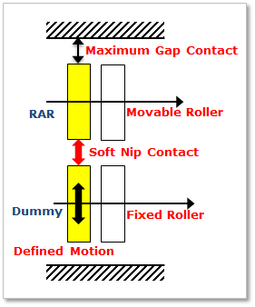
Figure 24.29 Soft nip and Maximum gap
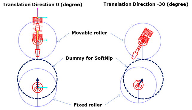
Figure 24.30 Soft nip
If a maximum gap is specified, a stopper activates when the Movable roller displacement reaches the designated value. In this case, RAR to base body contact is automatically created and its contact type is a point to circle contact. The contact radius and the point are determined by the radius of movable roller and the value of maximum gap, respectively.