35.2. HAT Type B
The schematic diagram of the Type B analysis model is shown in Figure 35.11.
The check ball is acted upon by the spring force and the hydraulic force from the cylinder.
The motion of the check ball is also assumed to act in the same direction as the cylinder.
The check ball is contacted to the cylinder.
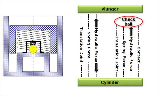
Figure 35.11 Schematic diagram of Type B analysis model
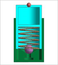
Figure 35.12 Geometry of Type B
35.2.1. Modeling Options
Point, Point, WithDialog
Point: Selects a point to a reference point of HAT.
Point: Selects a point to a direction point of HAT.
WithDialog: Modifies the property for the HAT. The HAT is created with clicking OK.
35.2.2. Properties
The user can modify the properties of HAT in the following dialog box:
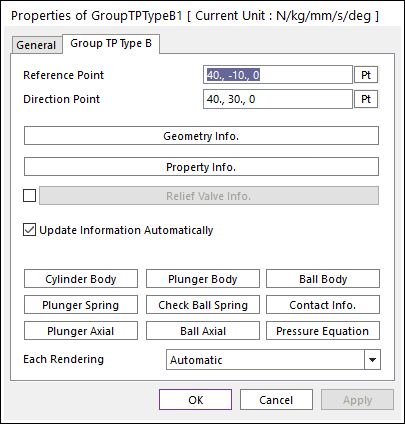
Figure 35.13 Type B Group property page
Reference Point: Defines the end point of cylinder body.
Direction Point: Defines the direction point of HAT.
Geometry Info.: Accesses the Geometry Information dialog box.
Property Info.: Accesses the Property Information dialog box.
Relief Valve Info.: Accesses the Relief Valve Information dialog box.
Update Information Automatically: Update the properties of bodies, the properties of springs, the properties of contact, the expression of Plunger Axial force and Ball Axial force, and the Pressure Equation.
Each Rendering: The selected mode can be displayed in Each Render mode.
Geometry Info.
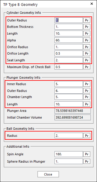
Figure 35.14 Type B Geometry Information dialog box
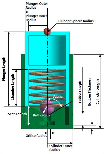
Figure 35.15 Schematic of Type B geometry
Spin Angle & Sphere Radius in Plunger
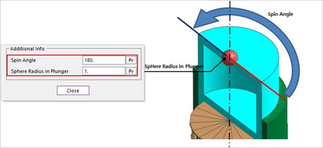
Figure 35.16 Spin Angle
Property Info.
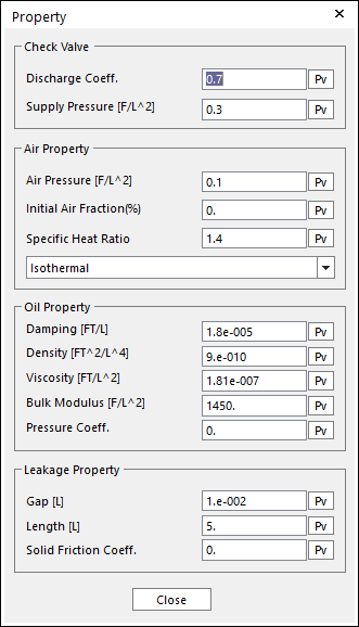
Figure 35.17 Type B Property dialog box
Relief Valve Info.
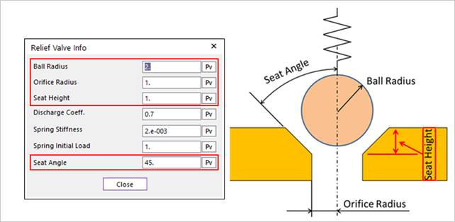
Figure 35.18 Relief Valve dialog box
This valve is a virtual valve for Type B.