30.2.9. Group Guide Arc
A chain slack is eliminated by supporting the entire return side with a guide and installing a take-up on the driven shaft. The chain may vibrate considerably due to the characteristic frequency of the chain, impact period of the driven shaft, or the polygonal action of the chain and sprocket. Therefore, it is a very important to install a guide shoe to prevent vibration. The width and length of the contact surface of the guide must be large enough for the chain link to pass. A group guide consists of guide segments, revolute joints and rotational spring dampers.
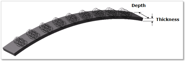
Figure 30.63 GroupGuideArc
30.2.9.1. Modeling Options
The user can create a guide as follows.
MultiPoint, WithDialog
MultiPoint: Selects some points to define the guide.
WithDialog: Modifies the property for the guide. The guide is created with clicking OK.
30.2.9.2. Properties
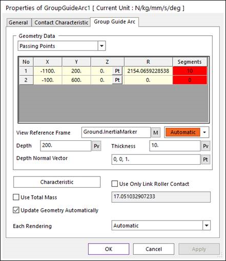
Figure 30.64 Group Guide Arc property page
The Group Guide Arc property page is shown in Figure 30.64. The parameters are explained below.
Geometry Data: There are 3 type methods to define a guide geometry. Those are Passing Points, Center Points and Radius, and Center Points and Arc Angle.
Passing Points
X, Y, Z: Defines a passing point of the guide based on View Reference Frame.
R: Defines a radius of the guide passing two points.
Segments: Displays the number of segments in the guide. This can be defined when creating the guide.
Center Points and Radius: Defines geometry data by using center points and radius.
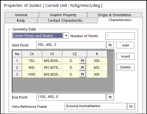
Figure 30.65 Guide property page [Characteristic page]
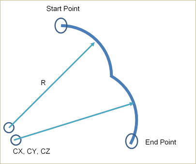
Figure 30.66 Definition for each data
Start Point: Defines a start point of the guide.
End Point: Defines an end point of the guide.
CX, CY, CZ: Defines a center point of the guide based on View Reference Frame.
R: Defines a radius of the guide with the center point.
Center Points and Arc Angle: Defines geometry data by using center points and arc angle.
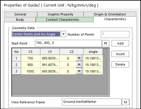
Figure 30.67 Guide property page [Characteristic page]
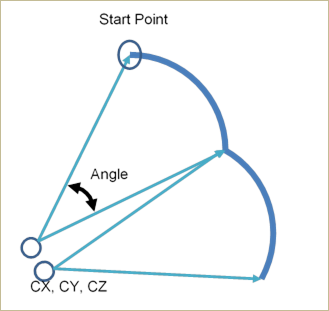
Figure 30.68 Definition for each data
Start Point: Defines a start point of guide.
CX, CY, CZ: Defines a center point of the guide based on View Reference Frame.
Angle: Defines a revolution angle of the guide.
View Reference Frame: Defines a reference frame for points.
Color: Selects the color of the guide.
Depth: Defines the depth of the guide.
Thickness: Defines the thickness of the guide.
Depth Normal Vector: Defines the direction to apply the depth of the guide.
Characteristic: Defines characteristic values for Rotational Springs.
Use Only Link Roller Contact: If the guide has narrower width than the pin length of a chain link, its function supports the contact between the Guide with the narrow width and the Roller Link of Roller and Multiplex.
Use Total Mass: Applies total Mass to each GuideArc body. If using Use Total Mass option, each GuideArc body has same mass which is divide by the segment number. The body’s Material Input Type is set as Density.
Update Geometry Automatically: If this option is unchecked, the position and orientation of the geometry constituting the group are not updated depending on variables in the property page. So, after executing Extract function, this option is unchecked.
Each Rendering: The selected mode can be displayed in Each Render mode.
30.2.9.2.1. Contact between a Guide and a Link
The guide rail is in contacts with the chain link in the two parts.
The surface of guide rail – the top/bottom surface of chain link plates
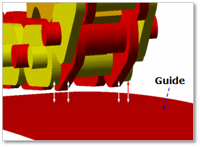
Figure 30.69 Contact between a guide and chain links
If the roller diameter of chain link is bigger than the height of roller link plate, the contact occurs as follows.
The surface of guide rail – the roller of chain link
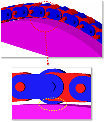
Figure 30.70 Contact between a guide and roller of chain links
If the guide width is narrower than the pin length of chain links, the contact happens when checking the option of Use Only Link Roller Contact.
The surface of the narrow guide rail – the roller link of chain links
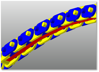
Figure 30.71 Contact between the narrow guide and chain links