31.1.3. Spur Gear
A spur gear is composed of a single body. Gear geometries are created from the parameters of ISO standards. The tooth profile is represented by multiple arcs. The gear tooth geometry data is:
Created from a predefined data file.
Edited from a predefined data file.
Exported from a predefined data file.
Imported from a predefined data file.
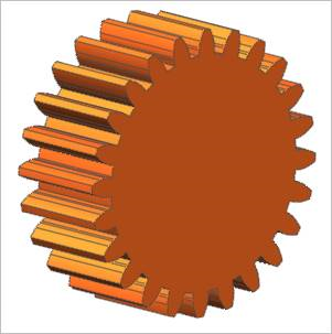
Figure 31.11 Spur Gear
31.1.3.1. Properties
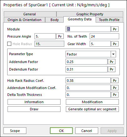
Figure 31.12 Spur Gear property page [Geometry Data page]
The Spur Gear property page is shown in Figure 31.12. The parameters are explained below. In order to understand the geometry, refer to Geometric Entities.
Module: Enters the module of the gear.
Pressure Angle: Enters the pressure angle of the gear.
No. of Teeth: Enters the number of teeth. The maximum number of teeth of gear is 400.
Hole Radius: Create a gear with a hole as the inputted radius.
Gear Width: Enters the width of the gear.
Parameter Type: two methods are supported to define the Addendum and Dedendum.
Factor: Defines the addendum and dedendum as factors. For more information, click here.
Addendum Factor: Enters the factor to define the addendum.
Dedendum Factor: Enters the factor to define the dedendum.
Addendum Radius & Whole Depth: Defines the addendum and dedendum as addendum radius and whole depth. For more information, click here.
Addendum Radius: Enters the addendum radius for the gear.
Whole Depth: Enters the whole depth as summation for the addendum and dedendum.
Hob Rack Radius Coef.: Enters the coefficient to define the hob rack radius. The default value is 0.38 (ISO 53, JIS Standard) and this should be equal or larger than 0. For more information, click here.
Note
In order to apply these values, The number of Under-Cut Arc should be defined in Tooth Profile page. For more information, click here.
Addendum Modification Coef.: Enters the coefficient to define the addendum.
Delta Tooth Thickness: Enters the delta value to define the tooth thickness. For more information, click here.
Information: Shows the calculated values for Pitch Radius, Tip Radius, Base Radius, Root Radius, and Circular Tooth Thickness.
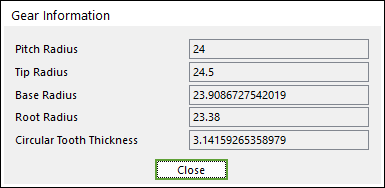
Figure 31.13 Gear Information dialog box
Modification: This function supports modification of gear tooth. Refer to Gear Tooth Modification.
Draw: All data must be defined with respect to the tooth marker. You can move points graphically by using the mouse directly.
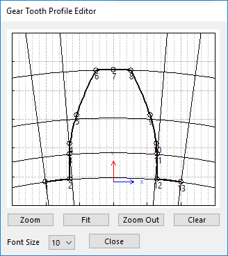
Figure 31.14 Gear Tooth Profile Editor dialog box
Generate optimal arc segment: In order to apply the modification of tooth, this button should be clicked.
Gear Tooth Modification
By fault in making and assembling the gear, the problems such like transmission error, noise and load concentration can be occurred. In order to reduce or optimize these gear problems, the gear tooth modification is applied along the flank or profile. Therefore, to simulate the dynamic behavior of gear modification effect, RecurDyn/Gear toolkit supports crowning, helix slope and tip relief gear modification. And also, it is allowed to define the left/right gear flank modification individually. So, user can analyze an asymmetric gear effect, too.
Definition of Right/Left Flank of Gear Tooth
The right flank (or left flank) is defined by Figure 31.15. The definition of right-hand/left hand tooth flank are defined with respect to datum face and that are in accordance with ISO 21771.
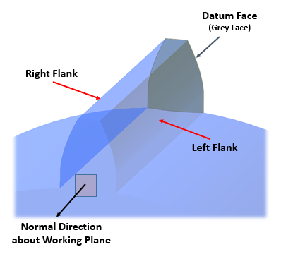
Figure 31.15 The Definition of Right/Left Flank
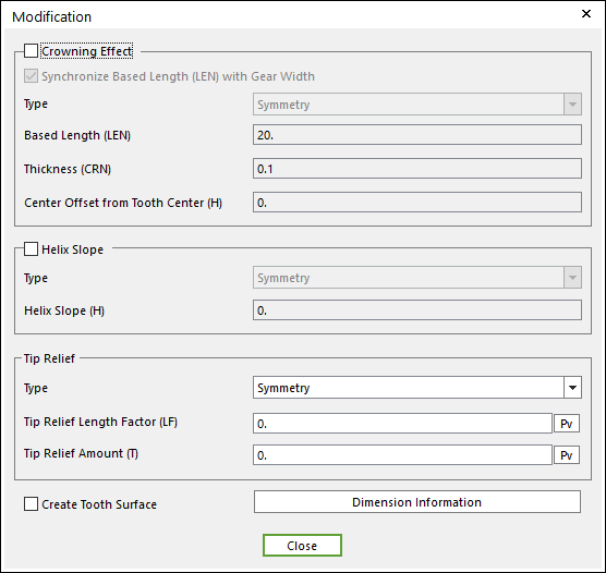
Figure 31.16 Modification dialog box
Crowning Effect
Crowning is the continuously increasing relief on the flank line from a common defined point of the main geometry, symmetrically in the direction of both ends of the tooth. And, crowning function should be applied to create the extruded gear tooth by using a quadratic curve which is defined three parameters such as LEN, CRN and H as shown in the Figure 31.17. Especially, this crowning modification helps to solve the edge loading problem of gear tooth.
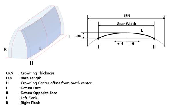
Figure 31.17 The Definition of Crowning Effect
Crowning Effect: If this option is checked, crowning effect function is activated.
Synchronize Based Length (LEN) with Gear Width: The LEN value is set as same value of Gear Width. If the user wants to define the LEN as your own value, check off the option. And then, you can input the LEN value to the input field.
Type: If the user wants to make asymmetrical crowning effect to the gear tooth, change the Type from Symmetry (default) to Asymmetry. Then, the user can input the Left/Right crowning effect values individually.
Based Length (LEN): Enters the based length of tooth.
Thickness (CRN): Enters the crowning thickness of tooth.
Center Offset from Tooth Center (H): Enters the offset value form tooth center.
Helix Slope Effect
Helix Slope modification is the continuously increasing removal of material from datum face to opposite face as shown Figure 31.18. Especially, helix slope modification is applied to get a uniform load distribution to the face width to increase the gear lifetime.
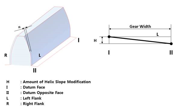
Figure 31.18 The Definition of Helix Slope Effect
Helix Slope: If this option is checked, helix slope function is activated.
Type: If the user wants to make asymmetrical Helix Slope effect to the gear tooth, change the Type from Symmetry (default) to Asymmetry. Then, you can input the Left/Right Helix Slope effect values individually.
Helix Slope (H): Inputs the helix slope value to the input field. Also, in the case helix slope effect, it is available to change the helix direction according to helix slope value. If you input the positive helix slope value, the helix slope modification is the continuously increasing removal from datum face to opposite face as Figure 31.19 (a). However, if you input the negative helix slope value, the helix slope modification is the continuously increasing removal form opposite face to datum face as Figure 31.19 (b).
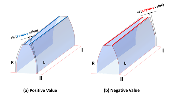
Figure 31.19 Helix Slope Effect according to Helix Slope value
Tip Relief Effect
Tip Relief is the continuously increasing reliefs of the transverse profile of the main geometry from defined points in the direction of the tip as shown Figure 31.20. Especially, tip relief modification is applied to reduce Transmission Error for high loaded gears.
Note
In order to apply these values, The number of Tip Relief Arc should be defined in Tooth Profile page. For more information, click here.
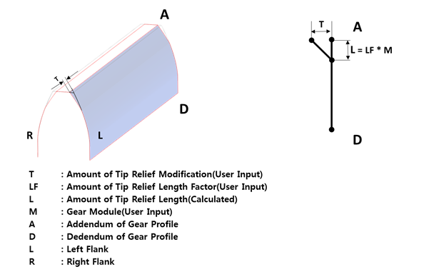
Figure 31.20 The Definition of Tip Relief Effect
Type: If you want to make asymmetrical Tip Relief effect to the gear tooth, change the Type from Symmetry (default) to Asymmetry. Then, you can input the Left/Right Tip Relief effect values individually.
Tip Relief Length Factor (LF): Enters the factor to define Tip Relief Length by Gear Module multiply (L=M x LF).
Tip Relief Amount (T): Enters the Tip Relief Amount.
The maximum of Tip Relief Amount & Tip Relief Length Factor are limited as like below Figure 31.21. So, tip relief amount must be less than 0.02 x Gear Module and tip relief length factor must be less than 0.6 factor.
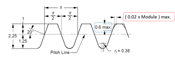
Figure 31.21 The Limitation of Tip Relief Amount & Length Factor
Create Tooth Surface: If this option is checked, a face surface is created for the gear tooth. It is very useful to define a contact entity.
Note
It is only available to define the gear tooth modification functions to spur and helical gear. Also, when user defines gear tooth modification such as Crowning and Helix Slope to spur and helical gear, user can only use 3D contact (Surface to Surface contact) or 3D Contact R (Solid Contact) between the gear pair.