24.8.4. PGuide Edge
The user can define a circle-shaped guide.
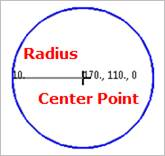
Figure 24.93 PGuide Edge
24.8.4.1. Modeling Options
The user can create the pedge guide as follows.
Point, Radius
Point: Selects a point to define the center of the circle guide.
Radius: Defines a radius of the circle guide.
Guide, OrthoDirection, Radius
Guide: Selects a linear guide to define the position of the circle guide.
OrthoDirection: Defines an orthotropic direction for the linear guide.
Radius: Defines a radius of the circle guide.
GuideMotherBody, Point, Radius
GuideMotherBody: Selects a body to define the parent body of the circle guide.
Point: Selects a point to define the center of the circle guide.
Radius: Defines a radius of the circle guide.
24.8.4.2. Properties
The properties dialog box of the PGuide Edge has three tabs.
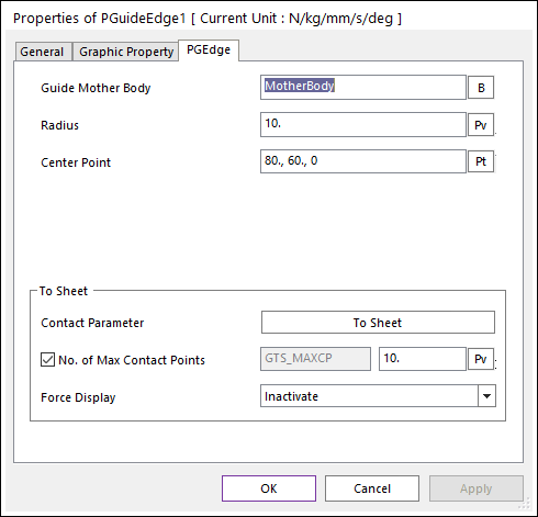
Figure 24.94 PEdge Guide property page
Guide Mother Body: Selects the mother body of PGuide Edge by clicking B.
Radius: Defines the radius of PGuide Edge.
Center Point: Defines the center point of PGuide Edge.
Contact Parameter: Allows the user to modify contact parameters by clicking To Sheet. In this dialog box, the user can modify the contact parameters of contact forces applied between the sheet and the guide. Refer to Contact formulas for MTT2D.
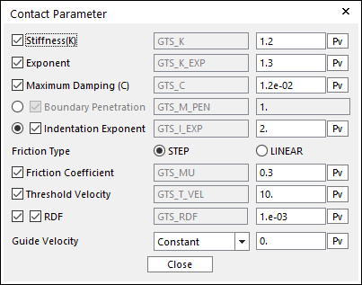
Figure 24.95 Contact Parameter dialog box
No. of Max Contact Points: Defines the number of max contact point for output. User can define this value from 1 to 5000. This value only affects Force Display and RPLT data about the contact points. The default value is 10.
Force Display: Graphically displays the all contact force vectors (the sum of the normal and tangential contact force) at each contact point up to the No. of Max Contact Point.