31.2.2. Web with Imprinted Edge
This page defines the making web with imprinted edge for the flexible web gear. The web is rigid body with imprinted edge where FDR is created in the Mesh operation. (This option only applied external gear)
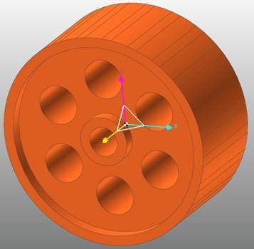
Figure 31.82 Web with imprinted Edge
31.2.2.1. Modeling Options
The user can create a rigid web geometry as follows.
Point, WithDialog
Point: Selects a point to define the center of the web geometry.
WithDialog: Defines the property for the web geometry. The web geometry is created with clicking OK.
Point, Direction, WithDialog
Point: Selects a point to define the center of the web geometry.
Direction: Defines a normal direction of the web geometry.
WithDialog: Defines the property for the web geometry. The web geometry is created with clicking OK.
Point, GearBody, WithDialog
Point: Selects a point to define the center of the web geometry.
GearBody: Selects a gear body created in RecurDyn. The information for geometry data and tooth profile of the selected gear body is used.
WithDialog: Defines the property for the web geometry. The web geometry is created with clicking OK.
Point, GearBody, Direction, WithDialog
Point: Selects a point to define the center of the web geometry.
GearBody: Selects a gear body created in RecurDyn. The information for geometry data and tooth profile of the selected gear body is used.
Direction: Defines a normal direction of the web geometry.
WithDialog: Defines the property for the web geometry. The web geometry is created with clicking OK.
31.2.2.2. Properties
Web tab defines the detail shape of the web. The Geometry Data and Tooth Profile tab refers to the Spur/Helical Gear Profile. (This gear Geometry Data and Tooth Profile are using all processor of flexible web gear)
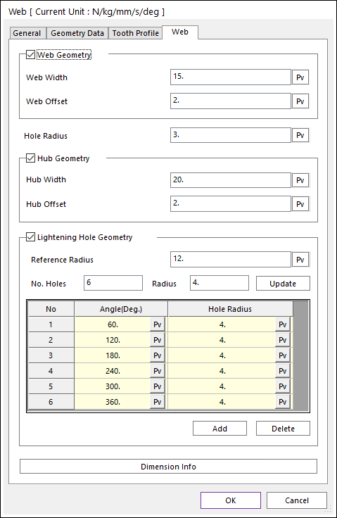
Figure 31.83 Web property page [Web page]
The Web property page is shown in Figure 31.83. The parameters are explained below. In order to understand the geometry, refer to Dimension info.
Web Geometry: defines the web width (Web Thickness) and web offset (Rim Thickness).
Web Width: defines the thickness of the web outer.
Web Offset: this value is applied in the direction that decrease from gear root radius.
Hole Radius: defines the hub radius of the web.
Hub Geometry: defines the hub width (Hub Length) and the hub offset.
Hub Width: defines the thickness of the web hub in the width direction.
Hub Offset: this value is applied in the direction that increase from the Hole Radius.
Lightening Hole Geometry: Create a web with a hole as the inputted radius.
Reference Radius: defines the radius where the center point of the lightening hole to be created is located.
No. Holes: defines how many holes to create on the circumference.
Radius: defines the radius of each holes.
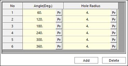
Figure 31.84 Table of Lightening Hole Geometry
Dimension Info: Shows the web shape definition.
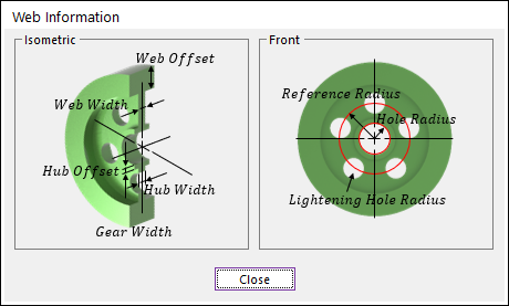
Figure 31.85 Dimension info dialog