4.7.1.13. Stress
4.7.1.13.1. STRESS
The STRESS function returns the stress acting on a designated node on a flexible body.
Format
Using reference marker
STRESS(Node id, Type, RMarker{, Position})
Using 3 reference nodes
STRESS(Node id, Type, Node id, Node id, Node id{, Position})
Arguments definition
NodeID |
Node number, including the names of the FFlex or RFlex Body, or argument number for the nodes to calculated for the stress value |
|||||||||||||||||||||||||||||||||||||||||||||||||||||||||||||
Type |
Symbol that indicates the type of stress to measure
|
|||||||||||||||||||||||||||||||||||||||||||||||||||||||||||||
SettingReferenceFrame |
R Marker |
The name or argument number of the standard marker for direction to be measured |
||||||||||||||||||||||||||||||||||||||||||||||||||||||||||||
3 reference nodes |
The name or argument number of the 3 reference nodes which define reference frame to be measured |
|||||||||||||||||||||||||||||||||||||||||||||||||||||||||||||
Position |
Recovery Position for FFlex output node
If the recovery position is not specified, the default value is the TOP for shell and MD for beam. If the RFlex body has only one stress shape, this argument is ignored. |
Reference Frame defined by 3 reference nodes
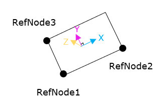
Figure 4.75 Definition of 3 nodal points reference frame
The reference frame defined by 3 nodal points is like above figure. X direction is parallel to the vector from reference node1 to reference node2 and Z direction is normal to the face which consist of 3 nodal points.
Example
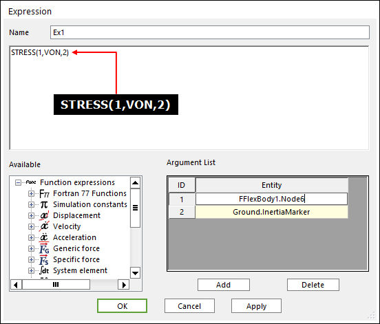
Figure 4.76 Example Expression using Stress function using RM

Figure 4.77 Example Expression using Stress function using 3 reference nodes
Note
The stress expression must not be used to apply the dependent force. Only the expression is used in the post procedure. In order to see the stress result for non-output nodes in Scope Expression, all component such as SX, SY etc should be included in output files.
4.7.1.13.2. STRAIN
The STRAIN function returns the strain acting on a designated node on a flexible body.
Format
Using reference marker
STRAIN(Node id, Type, RMarker{, Position})
Using 3 reference nodes
STRAIN(Node id, Type, Node id, Node id, Node id{, Position})
Arguments definition
Node ID |
Node number, including the names of the FFlex or RFlex Body, or argument number for the nodes to calculated for the strain value |
|||||||||||||||||||||||||||||||||||||||||||||||||||||||||||||
Type |
Symbol that indicates the type of strain to measure
|
|||||||||||||||||||||||||||||||||||||||||||||||||||||||||||||
SettingReferenceFrame |
RMarker |
The name or argument number of the standard marker for direction to be measured |
||||||||||||||||||||||||||||||||||||||||||||||||||||||||||||
3 reference nodes |
The name or argument number of the 3 reference nodes which define reference frame to be measured |
|||||||||||||||||||||||||||||||||||||||||||||||||||||||||||||
Position |
Recovery Position for FFlex output node
If the recovery position is not specified, the default value is the TOP for shell and MD for beam. If the RFlex body has only one stress shape, this argument is ignored. |
Reference Frame defined by 3 reference nodes
Figure 4.78 Definition of 3 nodal points reference frame
The reference frame defined by 3 nodal points is like above figure. X direction is parallel to the vector from reference node1 to reference node2 and Z direction is normal to the face which consist of 3 nodal points.
Example
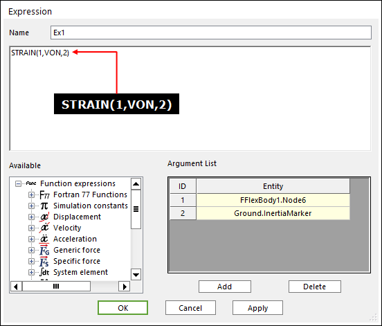
Figure 4.79 Example Expression using Strain function using RM
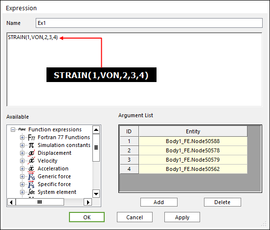
Figure 4.80 Example Expression using Strain function using 3 reference nodes
Note
The strain expression must not be used to apply the dependent force. Only the expression is used in the post procedure. In order to see the strain result for non-output nodes in Scope Expression, all component such as EX, EY etc should be included in output files.
4.7.1.13.3. STRESS_MINMAX
The STRESS_MINMAX function returns the maximum or minimum nodal stress in a node set generated from a flexible body.
Format
Using reference marker
STRESS_MINMAX(NodeSetID, MinMaxFlag, Type, RMarker{, Position})
Using 3 reference nodes
STRESS_MINMAX(NodeSetID, MinMaxFlag, Type, Node id, Node id, Node id{, Position})
Arguments definition
NodeSetID |
Node set number, including the names of the FFlex or RFlex Body, or argument number for the Node set to be calculated for the stress value |
|||||||||||||||||||||||||||||||||||||||||||||||||||||||||||||
MinMaxFlag |
Flag for min/max. 1 : min, 2 : max |
|||||||||||||||||||||||||||||||||||||||||||||||||||||||||||||
Type |
Symbol that indicates the type of stress to measure
|
|||||||||||||||||||||||||||||||||||||||||||||||||||||||||||||
SettingReferenceFrame |
R Marker |
The name or argument number of the standard marker for direction to be measured |
||||||||||||||||||||||||||||||||||||||||||||||||||||||||||||
3 reference nodes |
The name or argument number of the 3 reference nodes which define reference frame to be measured |
|||||||||||||||||||||||||||||||||||||||||||||||||||||||||||||
Position |
Recovery Position for FFlex output node
If the recovery position is not specified, the default value is the TOP for shell and MD for beam. If the RFlex body has only one stress shape, this argument is ignored. |
Reference Frame defined by 3 reference nodes
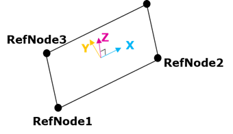
Figure 4.81 Definition of 3 nodal points reference frame
The reference frame defined by 3 nodal points is like above figure. X direction is parallel to the vector from reference node1 to reference node2 and Z direction is normal to the face which consist of 3 nodal points.
Example
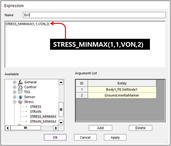
Figure 4.82 Example Expression using STRESS_MINMAX function using RM

Figure 4.83 Example Expression using STRESS_MINMAX function using 3 reference nodes
Note
The STRESS_MINMAX expression must not be used to apply the dependent force. Only the expression is used in the post procedure.
4.7.1.13.4. STRAIN_MINMAX
The STRAIN_MINMAX function returns the maximum or minimum nodal strain in a node set generated from a flexible body.
Format
Using reference marker
STRAIN_MINMAX(NodeSetID, MinMaxFlag, Type, RMarker{, Position})
Using 3 reference nodes
STRAIN_MINMAX(NodeSetID, MinMaxFlag, Type, Node id, Node id, Node id{, Position})
Arguments definition
NodeSet ID |
Node set number, including the names of the FFlex or RFlex Body, or argument number for the Node set to calculated for the strain value |
|||||||||||||||||||||||||||||||||||||||||||||||||||||||||||||
MinMaxFlag |
Flag for min/max. 1 : min, 2 : max |
|||||||||||||||||||||||||||||||||||||||||||||||||||||||||||||
Type |
Symbol that indicates the type of strain to measure
|
|||||||||||||||||||||||||||||||||||||||||||||||||||||||||||||
SettingReferenceFrame |
R Marker |
The name or argument number of the standard marker for direction to be measured |
||||||||||||||||||||||||||||||||||||||||||||||||||||||||||||
3 reference nodes |
The name or argument number of the 3 reference nodes which define reference frame to be measured |
|||||||||||||||||||||||||||||||||||||||||||||||||||||||||||||
Position |
Recovery Position for FFlex output node
If the recovery position is not specified, the default value is the TOP for shell and MD for beam. If the RFlex body has only one stress shape, this argument is ignored. |
Reference Frame defined by 3 reference nodes
Figure 4.84 Definition of 3 nodal points reference frame
The reference frame defined by 3 nodal points is like above figure. X direction is parallel to the vector from reference node1 to reference node2 and Z direction is normal to the face which consist of 3 nodal points.
Example
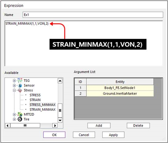
Figure 4.85 Example Expression using STRAIN_MINMAX function using RM
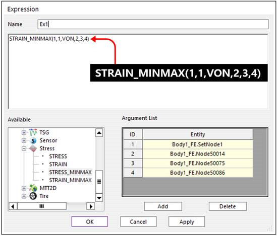
Figure 4.86 Example Expression using STRAIN_MINMAX function using 3 reference node
Note
The STRAIN_MINMAX expression must not be used to apply the dependent force. Only the expression is used in the post procedure.