42.2.2.1.6. Properties
Assembly consists of 3 property pages. Assembly Body List, Assembly Force List, and Assembly Contact List
Assembly Body List
You can open the scope of each assembly body by clicking the SC button.
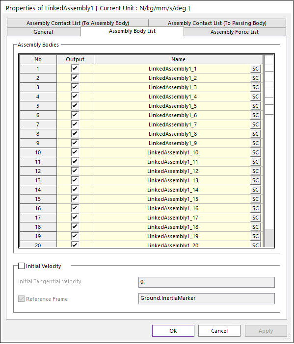
Figure 42.34 Assembly Body List property Page
Output: Check to write the body information in the rplt file.
Initial Velocity
Initial Tangential Velocity: Define the initial velocity for the x-translational direction of the center marker of each assembly body. If using Reference Frame option, PV could not be applied.
Reference Frame: If this option is checked, the initial velocity is set as different values for x-translational and y-translational directions with respect to Reference Frame.
Assembly Force List : When creating an assembly, Matrix Force or Bushing Force is created according to the connecting force type.
You can open the corresponding force property page by clicking the P button
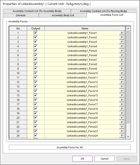
Figure 42.35 Assembly Force List property Page
Output : Check to write the force information in the rplt file.
Assembly Force for All : Apply force information to all assembly forces.
Assembly Contact List (To Assembly Body) : When creating an assembly, Geo Surface Contact can be created.
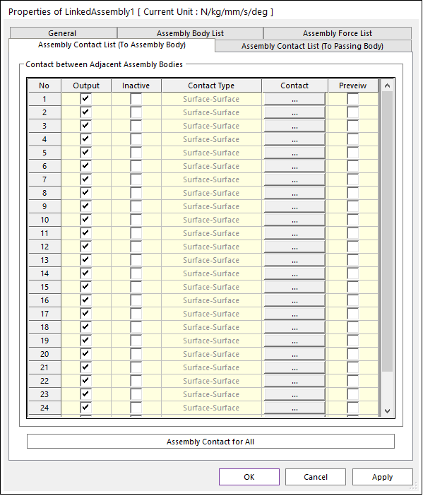
Figure 42.36 Assembly Contact List (To Assembly Body) property Page
Assembly Contact List (To Passing Body) : When creating an assembly, Geo Surface Contact or Geo Curve To Surface Contact or Geo Curve Contact is created according to the contact geometry.
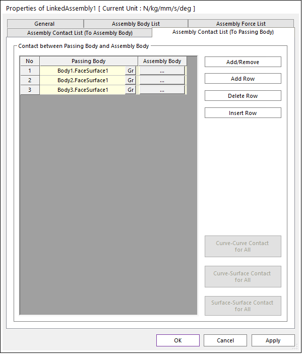
Figure 42.37 Assembly Contact List (To Passing Body) property Page
By clicking the Assembly Body button, you can open the Contact for Assembly Body dialog box where you can define the contact with each passing body.
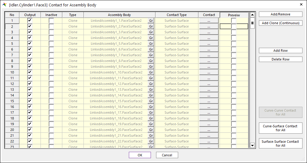
Figure 42.38 Contact for Assembly Body dialog box
Note
If contact type is curve to curve, you can define 2D or 3D curve type on property page. Geo Curve 2D Contact or Geo Curve 3D Contact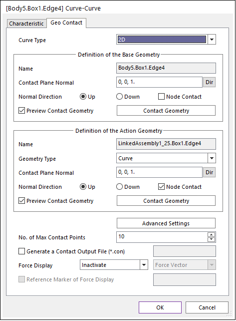
Figure 42.39 Curve To Curve Contact property Page
Output: Check to write the contact information in the rplt file.
Inactive: Check to inactivate the contact.
Contact: Open Contact Property Page corresponding to Contact Type.
Preview: If this option is checked, the patches making the contact surface are highlighted on the screen.
Add Clone (Continuous): When adding contact geometry, if the selected geometry has clone property, all body geometry with the same clone property is added as contact geometry.
Curve-Curve Contact for All: If there are Curve-Curve Contacts among the contacts connected to the passing body, the button is activated and the set parameters are applied to all Curve-Curve Contacts connected to the passing body.
Curve-Surface Contact for All: If there are Curve-Surface Contacts among the contacts connected to the passing body, the button is activated and the set parameters are applied to Curve-Surface Contacts connected to the passing body.
Surface-Surface Contact for All: If there are Surface-Surface Contacts among the contacts connected to the passing body, the button is activated and the set parameters are applied to Surface-Surface Contacts connected to the passing body.
Add/Remove: Select the assembly body and face of the entire passing body to define the contact.
Note
If you select the face of the passing body with the Add/Remove function, all existing contact information will be lost, so please be aware of this.
Add Row: Add a row to the Contact List.
Delete Row: Delete selected row to the Contact List.
Insert Row: Creates a row above the selected row.
Note
If you had not created a contact in the Assembly dialog, user can proceed to create it in the corresponding Assembly Property dialog.
Curve-Curve Contact for All: If there are Curve-Curve Contacts among the contacts included in the assembly, the button is activated and the set parameters are applied to all Curve-Curve Contacts included in the assembly.
Curve-Surface Contact for All: If there are Curve-Surface Contacts among the contacts included in the assembly, the button is activated and the set parameters are applied to all Curve-Surface Contacts included in the assembly.
Surface-Surface Contact for All: If there are Surface-Surface Contacts among the contacts included in the assembly, the button is activated and the set parameters are applied to all Surface-Surface Contacts included in the assembly.