20.6.13.1. PMDC Drive
PMDC Drive block is the block to model PMDC Machine and Controller to control PMDC Machine. Refer to PMDC.
Dialog Box
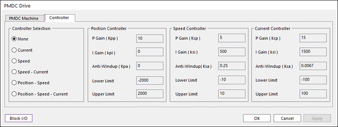
Figure 20.186 PMDC Drive dialog box
Parameter(s) |
Description |
Kcp |
Proportional gain of PMDC Current Controller. |
Kci |
Integral gain of PMDC Current Controller. |
Kca |
Anti-Windup gain of PMDC Current Controller. |
Lower Limit |
Output minimum value (Voltage) of PMDC Current Controller. |
Upper Limit |
Output maximum value (Voltage) of PMDC Current Controller. |
Parameter(s) |
Description |
Ksp |
Proportional gain of PMDC Speed Controller. |
Ksi |
Integral gain of PMDC Speed Controller. |
Ksa |
Anti-Windup gain of PMDC Speed Controller. |
Lower Limit |
Output minimum value (Current) of PMDC Speed Controller. |
Upper Limit |
Output maximum value (Current) of PMDC Speed Controller. |
Parameter(s) |
Description |
Kpp |
Proportional gain of PMDC Position Controller. |
Kpi |
Integral gain of PMDC Position Controller. |
Kpa |
Anti-Windup gain of PMDC Position Controller. |
Lower Limit |
Output minimum value (Speed) of PMDC Position Controller. |
Upper Limit |
Output maximum value (Speed) of PMDC Position Controller. |
20.6.13.1.1. Input Port and Output Port of PMDC Drive
Input signals
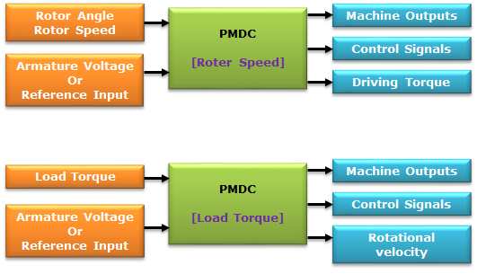
Table 20.119 1st Port Input data Mode
Input signal of 1st Port
Rotor Speed
Rotor Angle, Rotor Speed
Load Torque
Load Torque
Table 20.120 2nd Port Controller Mode
Input signal of 2nd Port
None
Armature Voltage
Current
Current Reference
Speed
Speed Reference
Speed + Current
Speed Reference
Position + Speed
Position Reference
Position + Speed + Current
Position Reference
Output signals
Table 20.121 1st Port No
Signal
Description
Unit
1
\(\theta\)
Is the rotor angle
rad
2
\(\omega\)
Is the rotor angular speed
rad/s
3
\({{I}_{a}}\)
Is the armature current
A
4
\({{T}_{e}}\)
Is the generated electrical torque
N.m
Table 20.122 2nd Port Controller Mode
Output signals of 2nd Port
None
None
Current
Armature Voltage
Speed
Armature Voltage
Speed + Current
Reference Current, Armature Voltage
Position + Speed
Reference Speed, Armature Voltage
Position + Speed + Current
Reference Speed, Reference Current, Armature Voltage
Table 20.123 3rd Port Input data Mode
Output signal of 3rd Port
Rotor Speed
Driving Torque
Load Torque
Rotor rotational Velocity
20.6.13.1.2. PMDC Controller
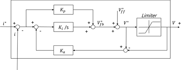
Figure 20.187 Current Controller
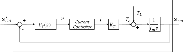
Figure 20.188 Speed + Current Controller
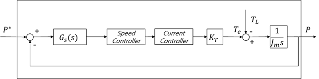
Figure 20.189 Position Controller
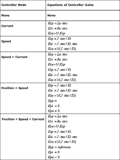
20.6.13.1.3. Design of Controller