36.5. Assembling a Timing Chain System
After creating geometric entities and connecting elements, perform assembly using Auto Assembly.
Click the Component icon of the Timing Chain group in the Timing Chain tab. The user can see the Timing Chain System Component Builder Dialog as follow.
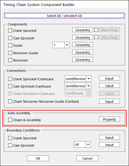
Figure 36.59 Timing Chain System Component Builder dialog box
Click Property for setting the Assembly Sequence and Attached Body. The user can see the TimingChain Assembly & Link Information dialog box as follow.
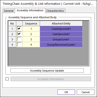
Figure 36.60 TimingChain Assembly & Link Information dialog box
Assembly Sequence Update: The user can select entities for assembly and set the sequence. If the user wants to set the sequence as selected attached entities automatically, clicks Assembly Sequence Update.
Assembly Information: If the user wants to change the number of the links, checks this option and sets the information as follow.
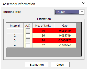
Figure 36.61 Assembly Information dialog box
Bushing Type: Selects the bushing type. The user can see busing information in the Assembly Information. To see more information, refer to Chain Bushing.
Estimation: Defines the number of links and gap. The user cannot change red intervals. These intervals depend on the sprocket only.
After defining the assembly information, Clicks OK with checking Chain & Assembly in the Timing Chain System Component Builder dialog box.
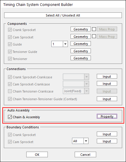
Figure 36.62 Timing Chain System Component Builder dialog box