11.2.2.1. Select Flexible Body
This type selects a FFlex body or RFlex body if there are several FFlex bodies and RFlex bodies in the model.
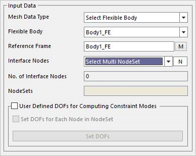
Figure 11.32 Mesh Data Type - Select Flexible Body
Flexible Body: Select a FFlex body or RFlex body in Working Window.
Reference Frame: Select the reference frame of the selected FFlex body or RFlex body.
Interface Nodes: Defines the constraint modes by selecting the connecting points which are nodes of a flexible body. For more information, refer to How to Set Interface Nodes.
User defined DOFs for Computing Constraint Modes
If this option is unchecked, all DOFs of interface nodes are used in constraint modes in CMS analysis. (This is default.)
If this option is checked, the generating constraint modes of the defined interface nodes can be controlled by defining the DOFs for interface nodes. By default, all DOFs of interface nodes are used in constraint modes in CMS analysis.
Set DOFs for Each Node in Node Set
If this option is checked, when “Select Multi Node Set” is used, user can define a single setting adapted to including all nodes of each node set
Set DOFs: Defines the DOFs of interface nodes for computing constraint modes through the dialog after clicking Set DOFs as shown below. User can set a special coordinate system each node or a node-set or node-sets for the constraint modes. The coordinate system is available Cartesian or Cylindrical coordinate system.
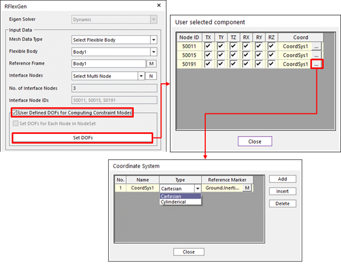
Figure 11.33 Using the Set DOFs option
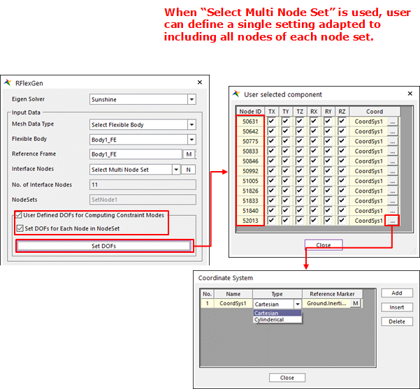
Figure 11.34 Using the Set DOFs option using Select Multi Node Set
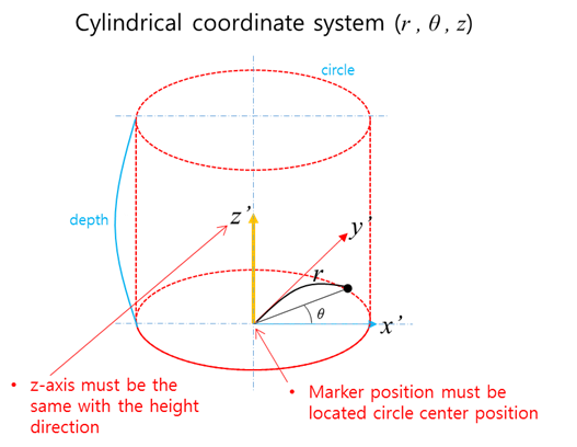
Figure 11.35 Cylindrical coordinate system at the SetDOFs option
Note
11.2.2.1.1. How to Set Interface Nodes
Generally, when applying a RFlex body to a MFBD model, it is needed to define the connecting points because Forces, Joints should be defined. At that time, it is necessary to add the constraint modes about the connecting points to the normal modes. This function makes you define the connecting points what it is called Interface Nodes. After that the Eigen solver should perform the CMS analysis which generates both constraint modes and normal modes. If Interface Nodes is not defined, the solver should perform just the Normal mode analysis. Four methods to define interface nodes are supported.
Select Multi Node: Possible to select the nodes of a FFlex body or a RFlex body in the working window directly with clicking nodes one by one after clicking N. This option is available when selecting Select Flexible Body in Mesh Data Type.
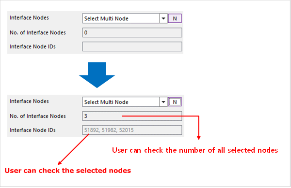
Figure 11.36 The Select Multi Node option
No. of Interface Nodes: Displays the number of selected interface nodes.
Interface Node IDs: Displays the selected interface node IDs.
Select Multi Node Set: Possible to set using two or more than two node sets.
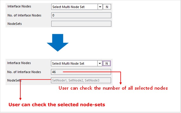
Figure 11.37 The Select Multi Node Set option
No. of Interface Nodes: Displays the number of selected interface nodes.
Node Set: Displays the name of selected node set.
Select Multi FDR: Possible to set using one or more than two FDR elements.
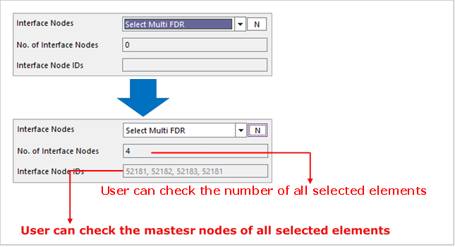
Figure 11.38 The Select Multi FDR option
No. of Interface Nodes: Displays the number of selected FDR elements.
Interface Node IDs: Displays primary node IDs of the selected FDR elements.
Direct Input: Possible to write the node IDs that are defined as the Interface nodes directly. In the case of Nastran Bulk File as Mesh Data Type, this method is only supported.
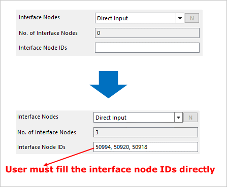
Figure 11.39 The Direct Input option
No. of Interface Nodes: Displays the number of selected interface nodes.
Interface Node IDs: Define interface node IDs directly.
Note
Shell9 and Solid26 elements are not supported in RFlexGen. So, if the user sets mid nodes to the Interface Node, RecurDyn give a waring message as bellows.
Warning
Mid-node cannot be included to the Interface Node or the BC of the RFlexGen. The selected Mid-Nodes are automatically ignored in the RFlexGen.