25.4. Roller Group
Definition of the rollers
A fixed roller is connected to a base body by a revolute joint and has one degree of freedom. A movable roller has two degrees of freedom for a translational and rotational motion. So, this group is consisted of two bodies, two joints, and one translational spring damper, as shown in Figure 25.23. The movable roller body is connected to a roller axis retainer (RAR) body by a revolute joint and the RAR is linked to a base body or ground by a translational joint and spring damper. The movable roller is dependent on the fixed roller. To delete the fixed roller, all related the movable rollers must be deleted.
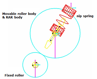
Figure 25.23 Definition of the rollers
Contact geometry of the rollers
The contact geometry of the roller is described as a cylinder that has a contact reference frame at the center point of one end side. The z-axis of the reference frame coincides with the depth direction of roller group dialog as shown in Figure 25.24 below.
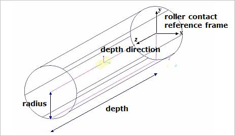
Figure 25.24 Contact geometry of a roller
Roller to Sheet Contact
The roller contacted to a sheet is described as a cylinder to line contact as shown in Figure 25.25. The roller can be contacted at the vertexes and in the edges of each patch. The cross points between a line of roller parallel to the depth direction and lines of sheet which consist the rectangular patches are first searched and examined whether the points are contacted. And then, the contact normal direction is determined, and the tangential direction is obtained from the normal direction and the specified depth direction by right hand rule.
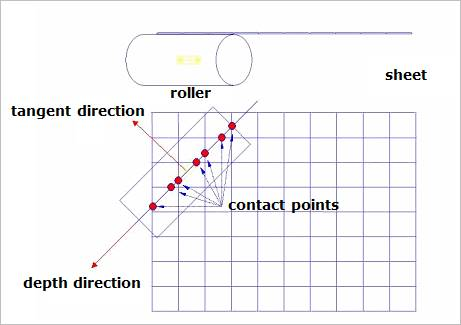
Figure 25.25 Roller to sheet contact
Roller to roller contact
The roller contact to a roller is described as a cylinder to cylinder contact shown in Figure 25.26. The roller can be contacted in two side edges and on the cylindrical face of the other roller. The contact normal direction is determined parallel to the relative position vector from the fixed roller to the movable roller and the tangential direction is obtained from the normal direction and the specified depth direction by right hand rule.
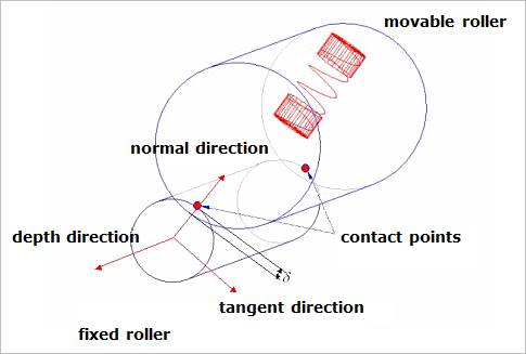
Figure 25.26 Cylinder to patch contact
Soft nip of the movable roller
The user can use a function expression of soft nip for adjusting a gap between two rollers. If soft nip is activated, a dummy roller connected to a base body by a translational joint is automatically created as shown in Figure 25.27. The translational direction of the dummy body for the soft nip is the same with the translation direction of the movable roller. The mass of the dummy roller is zero and a motion of the translation joint is defined with the user-specified function expression. And a roller axis retainer (RAR) to dummy contact is automatically created. The contact is described as a roller to roller contact and the contact radiuses are determined by those of the movable roller and the fixed roller. In this contact, only the normal force is generated.
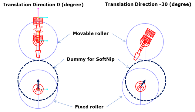
Figure 25.27 Soft nip
Maximum gap of the movable roller
If the maximum gap is specified, a stopper works when the movable roller displacement reaches to the specified value. In this case, RAR to base body contact is automatically created and its contact type is a cylinder to plane contact and the contact radius and the virtual plane are determine by the radius of a movable roller and the value of maximum gap, respectively. In this contact, only the normal force is generated.
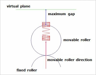
Figure 25.28 Maximum gap
Definition of multiple fixed rollers
Fixed rollers can have multiple contact teeth against a sheet and a movable roller as shown in Figure 25.29. To avoid a jamming or protect to transfer some sheets at once, the printer or ATM makers are used to design a roller with multiple teeth. In this case, the multi-roller function is useful.
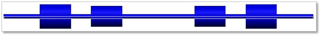
Figure 25.29 An example of multiple fixed roller