34.2.1. CamShaft (include Cam & CamSprocket)
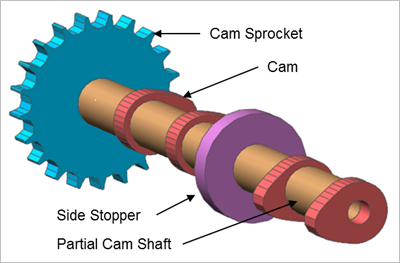
Figure 34.57 CamShaft
34.2.1.1. Properties
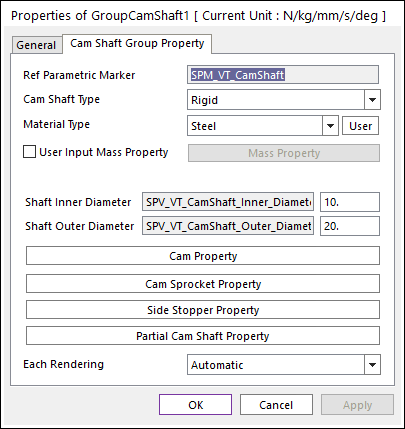
Figure 34.58 GroupCamShaft property page
Ref Parametric Marker: Controls the position of camshaft. It is also special parametric marker (SPM).
Cam Shaft Type: Selects the type of camshaft. It defines the connection method between multi bodies.
Material Type: Selects a material type. Three methods are supported.
Library: The user can select a material type supported from Material Library.
User: The user can create the user-defined material properties by clicking User. For more information, refer to Material Property.
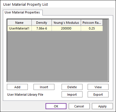
Figure 34.59 User Material Property List dialog box
User Input Mass Property: If it is checked, the user can modify the value of the mass and the moment of inertia directly by clicking Mass Property.
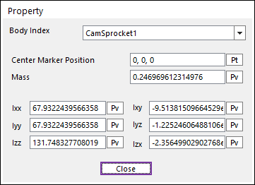
Figure 34.60 Property dialog box
Shaft Inner Diameter: Defines an inner diameter of camshaft.
Shaft Outer Diameter: Defines an outer diameter of camshaft.
Cam Property: Defines a shape of the cam.
Cam Sprocket Property: Defines some geometry data and property data of the Cam Sprocket.
Side Stopper Property: Defines some geometry data of the Side Stopper.
Partial Cam Shaft Property: Defines a position and some geometry data of the Partial Cam Shaft.
Each Rendering: The selected mode can be displayed in Each Render mode.
34.2.1.1.1. Cam Shaft Type
Rigid Type
All multi bodies are connected by fixed joint. It acts like one body.
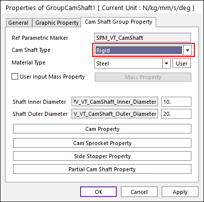
Figure 34.61 Cam Shaft property page [Rigid Type]
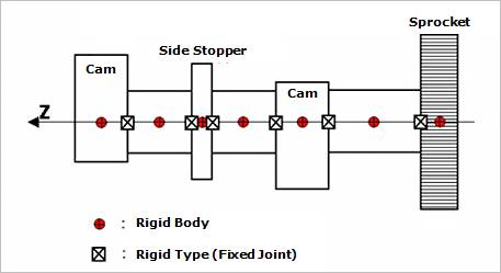
Figure 34.62 Rigid Type of the Cam shaft
Torsional Type
Multi bodies are connected by Revolute Joint and Rotational Spring Damper with Revolute Joint. It acts like flexible body.
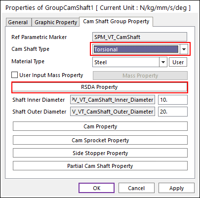
Figure 34.63 Cam Shaft property page [Torsional Type]
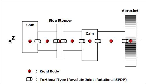
Figure 34.64 Torsional Type of the Cam shaft
The user can modify the property of rotational spring damper that connects multi bodies. For more information, refer to Rotational Spring Force.
If the user clicks RSDA Property, the user can see the following dialog box.
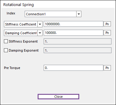
Figure 34.65 Rotational Spring dialog box
Torsional & Bending Type
Multi bodies are connected by Fixed Joint and Bushing Force. It acts like flexible body.

Figure 34.66 Cam Shaft property page [Torsional & Bending Type]
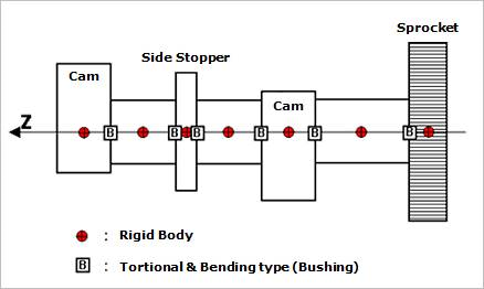
Figure 34.67 Torsional & Bending Type of the Cam shaft
The user can modify the property of bushing force that connects multi bodies. For more information, refer to Bushing Force.
If the user clicks Bushing Property, the user can see the following dialog box (Figure 34.68).
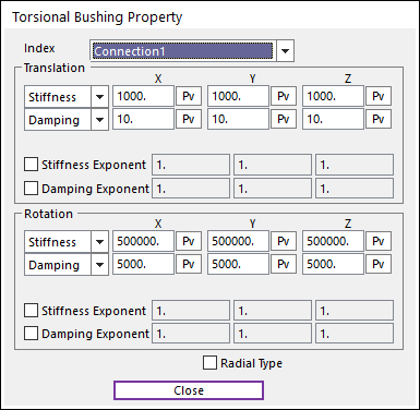
Figure 34.68 Torsional Bushing Property dialog box
Beam Type
Multi bodies are connected by Beam Force. It acts like flexible body.
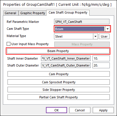
Figure 34.69 Cam Shaft property page [Beam Type]
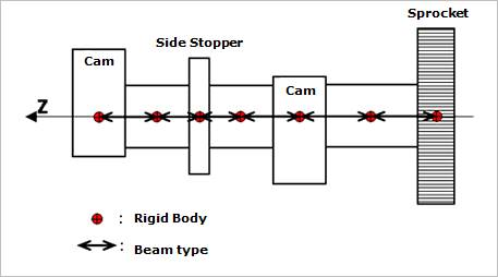
Figure 34.70 Beam Type of the Cam shaft
The user can modify the property of Beam Force that connects multi bodies. The user has to specify the value of Shear Modulus that is used to calculate Beam Force. For more information, refer to Beam Force.
If the user clicks Beam Property, the user can see the following dialog box.
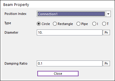
Figure 34.71 Beam Property dialog box
34.2.1.1.2. Cam Property
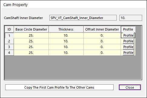
Figure 34.72 Cam Property dialog box
CamShaft Inner Diameter: Shows the inner diameter of camshaft.
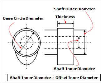
Figure 34.73 Definition of geometries
Base Circle Diameter: Defines a base circle diameter of cam.
Thickness: Defines a thickness of cam.
Offset Inner Diameter: Defines an offset inner diameter of cam. The inner hole diameter of the cam is defined as summation of the shaft inner diameter and the offset inner diameter.
Profile: The shape of the cam can be designed with cam angle and radius in the following dialog box.
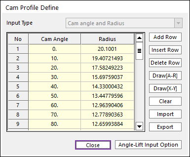
Figure 34.74 Cam Profile Define dialog box
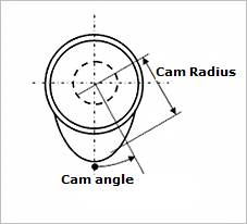
Figure 34.75 Cam Angle and Radius
Add Row: Adds a row to the end of the table.
Insert Row: Inserts a row where the cursor is and move the current and later rows down.
Delete Row: Deletes the row where the cursor is and move the later rows up.
Clear: Deletes all rows in the table.
Draw(A-R): The value of cam radius for cam angle is drawn. You can move points graphically by using the mouse directly.
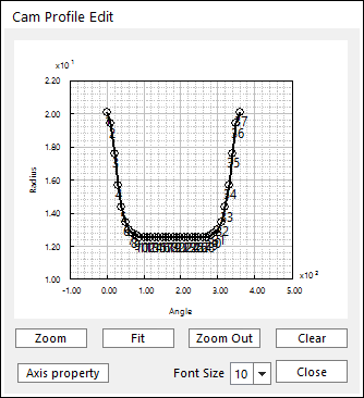
Figure 34.76 Cam Profile Edit dialog box
Draw(X-Y): The value of Y position for X position is drawn. You can move points graphically by using the mouse directly.
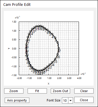
Figure 34.77 Cam Profile Edit dialog box
Clear: Deletes all rows in the table.
Import: Imports the cam angle and radius data pairs from a MAT file or a text file. In the case of the text file, the usage of the comma, the tab, and the space can be the delimiter between the three columns in the file. And when using the Excel file, the user can select the Tab-delimited text file output option or the CSV (Comma-Separated Values) file output option to save the Excel file which can be imported.
Export: Exports the cam angle and radius data pairs to a MAT file or a text file.
Angle-Lift Input Option: The shape of the cam can be designed with cam angle and cam lift in the following dialog box.
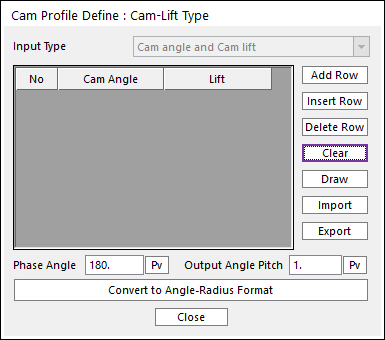
Figure 34.78 Cam Profile Define : Cam-Lift Type dialog box
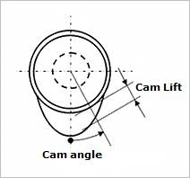
Figure 34.79 Cam Angle and Cam Lift
Add Row: Adds a row to the end of the table.
Insert Row: Inserts a row where the cursor is and move the current and later rows down.
Delete Row: Deletes the row where the cursor is and move the later rows up.
Clear: Deletes all rows in the table.
Draw: The value of cam lifter for cam angle is drawn. You can move points graphically by using the mouse directly.
Import: Imports the cam angle and lifter data pairs from a MAT file or a text file. In the case of the text file, the usage of the comma, the tab, and the space can be the delimiter between the three columns in the file. And when using the Excel file, the user can select the Tab-delimited text file output option or the CSV (Comma-Separated Values) file output option to save the Excel file which can be imported.
Export: Exports the cam angle and lifter data pairs to a MAT file or a text file.
Phase Angle
Output Angle Pitch
Convert to Angle-Radius Format
Copy The First Cam Profile To The Other Cams: Copies the first cam profile and the profile is applied to other cams.
34.2.1.1.3. Cam Sprocket Property
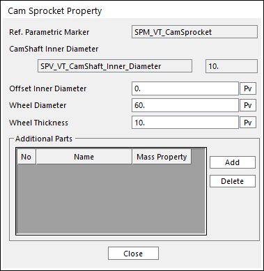
Figure 34.80 Cam Sprocket Property dialog box
Ref. Parametric Marker: Controls the position of cam sprocket. It is also special parametric marker (SPM).
CamShaft Inner Diameter: Shows the inner diameter of camshaft.
Offset Inner Diameter: Defines an offset inner diameter of cam sprocket. The inner hole diameter of the cam sprocket is defined as summation of the cam shaft inner diameter and the offset inner diameter.
Wheel Diameter: Defines a diameter of cam sprocket.
Wheel Thickness: Defines a thickness of cam sprocket.
34.2.1.1.4. Side Stopper Property
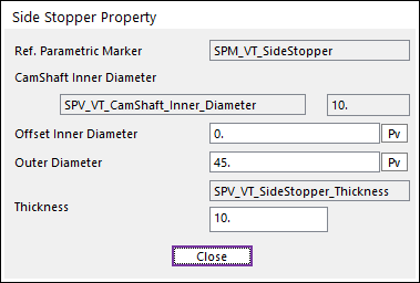
Figure 34.81 Side Stopper Property dialog box
Ref. Parametric Marker: Controls the position of cam sprocket. It is also special parametric marker (SPM).
CamShaft Inner Diameter: Shows the inner diameter of camshaft.
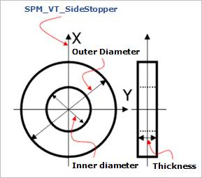
Figure 34.82 Definition of geometries
Offset Inner Diameter: Defines an offset inner diameter of side stopper. The inner hole diameter of the side stopper is defined as summation of the cam shaft inner diameter and the offset inner diameter.
Outer Diameter: Defines an outer diameter of side stopper.
Thickness: Defines a thickness of side stopper.
34.2.1.1.5. Partial Cam Shaft Property
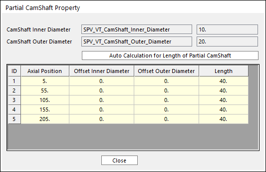
Figure 34.83 Partial CamShaft Property dialog box
CamShaft Inner Diameter: Shows the inner diameter of camshaft.
CamShaft Outer Diameter: Shows the outer diameter of camshaft.
Auto Calculation for Length of Partial CamShaft: The length of Partial Camshaft is calculated automatically.
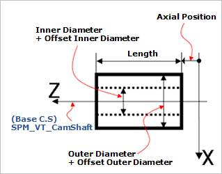
Figure 34.84 Definition of geometries
Axial Position: Defines the start position for the partial cam shaft.
Offset Inner Diameter: Defines an offset inner diameter of the partial cam shaft. The inner hole diameter of the partial cam shaft is defined as summation of the cam shaft inner diameter and the offset inner diameter.
Offset Outer Diameter: Defines an offset outer diameter of the partial cam shaft. The outer diameter of the partial cam shaft is defined as summation of the cam shaft outer diameter and the offset outer diameter.
Length: Defines a length of the partial cam shaft.