40.4.2.1. Geometry
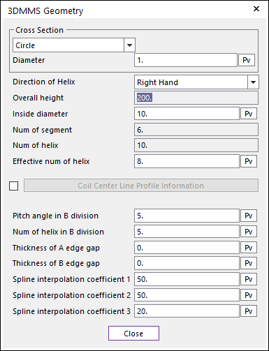
Figure 40.45 3DMMS Geometry dialog box
Cross Section: Defines the type of spring cross-section. It is used for automatic calculation of spring geometry and properties of beam forces. The center of the cross-section is located on the imaginary spline, which is defined the relationship between helix and height of spring.
Circle: Is the section option for circle type cross section spring.
Diameter: Defines the circle diameter of spring.
Sub-Oval: Is the section option for Sub-Oval type cross section spring. This cross section is divided circle area and oval area. Then, Width, Thickness, and Exponent are defined for the sub-oval option
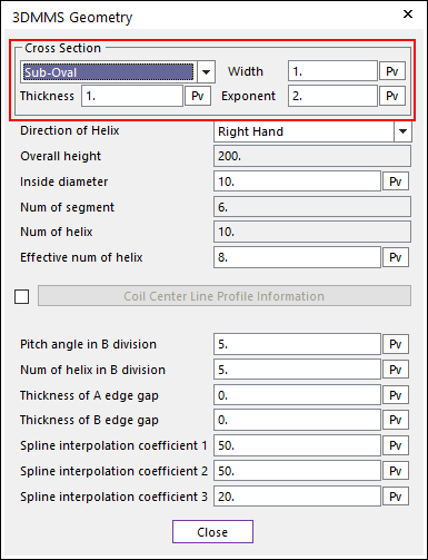
Figure 40.46 Selection Sub-Oval option of Cross Section
Width (\({{d}_{1}}\)): Defines the width of cross section.
Thickness (\({{d}_{2}}\)): Defines the thickness of the cross section.
Exponent (\(\alpha\)): Defines the exponential number to define the oval part of cross section in follow formulation.
\[\begin{flalign} & \left( \frac{x}{d_1/2}\right)^\alpha + \left( \frac{y}{d_2/2} \right)^\alpha = 1 \ \ \ \ \text{For the oval part} & \end{flalign}\]\[\begin{flalign} & x^2+y^2=(d_2/2)^2 \ \ \ \ \ \ \ \ \ \ \text{For the circle part} & \end{flalign}\]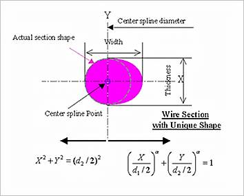
Figure 40.47 Cross Section of spring
Direction of Helix: Defines the direction for coiling of spring.
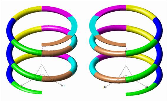
Figure 40.48 Right hand helix direction (right spring) & left hand helix direction (left spring)
Overall height (\({{H}_{0}}\)): Shows the total length of spring.
Inside diameter (\({{D}_{2}}\)): Defines the inside diameter of spring coil.
Outside diameter (\({{D}_{1}}\)): Is the outside diameter of spring coil. It is calculated internally. (\({{D}_{1}}={{D}_{2}}+2\times {{d}_{1}}\))
Central spline diameter (\({{D}_{s}}\)): Is the diameter for defining the origin of cross-section of wire. It is calculated internally. (\({{D}_{s}}={{D}_{1}}-{{d}_{2}}\))
Num of segment: Shows the number of segments in a helix
Num of helix (\({{N}_{r}}\)):** Shows the total number of helixes of spring.
Effective num of helix (\({{N}_{er}}\)): Shows the number of helixes which can work as spring actually.
Coil Center Line Profile Information: Defines the number of helix and radius along to height. For more information, click here.
Pitch angle in B division (\(\beta B\)): If some range coils is denser or sparser than other range, the upper part of this range is named B division and the other is named A division. Pitch angel in B division is the inclined angle of the line in the B division range of the imaginary spline for the center of cross-section of coil.
Num of helix in B division (\({{N}_{B}}\)): Shows the number of helixes in the B division.
Thickness of A edge gap (\({{I}_{1}}\)): Shows the gap between coils in the range of non-effective helices of bottom.
Thickness of B edge gap (\({{I}_{2}}\)): Shows the gap between coils in the range of non-effective helices of top.
Spline interpolation coefficient 1 (\({{RI}_{1}}\)): The lines in the below figure are connected with arcs. The blue and red line in below figure is connected with this RI1. The unit of this coefficient is mm always regardless the system unit.
Spline interpolation coefficient 2 (\({{RI}_{2}}\)): The red and green line in below figure is connected with this RI2. The unit of this coefficient is mm always regardless the system unit.
Spline interpolation coefficient 3 (\({{RI}_{3}}\)): The green and yellow line in Figure 40.49 is connected with this RI3. The unit of this coefficient is mm always regardless the system unit.
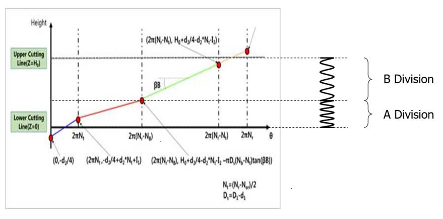
Figure 40.49 Imaginary spline for the center of cross-section of coil
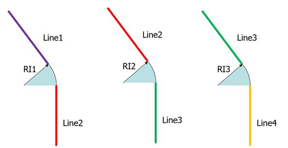
Figure 40.50 RI1, RI2, and RI3 for interpolation between lines
40.4.2.1.1. Coil Center Line Profile Information
This can define the number of helix and radius along to height.
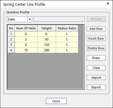
Figure 40.51 Spring Center Line Profile dialog box
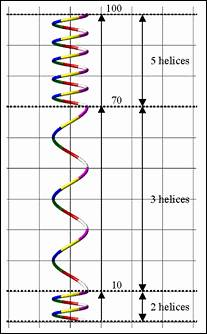
Figure 40.52 Spring center line profile dialogue
Radius Ratio: This ratio is necessary to change shape of spring continuously. If this ratio is used, special shaped spring (such as Beehive spring, conical spring and cylindrical spring) can be generated.
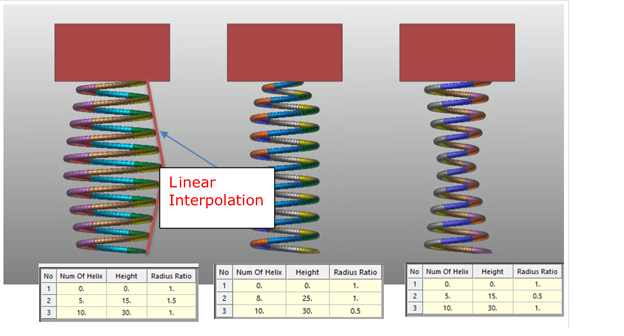
Figure 40.53 Spring center line profile dialogue as the Radius Ratio