33.2.3. Piston
A piston is composed of a single body.
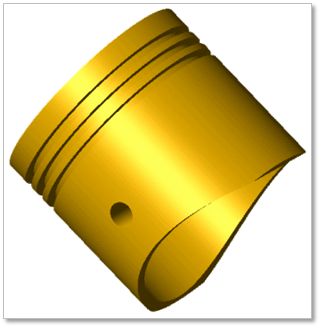
Figure 33.23 Piston
33.2.3.1. Modeling Options
Click the Piston icon of the Piston group in the Piston tab. The user can see the Crank Component - Piston dialog box.
The user can select the position where the piston pin is created in Component Index.
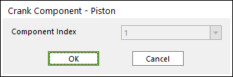
Figure 33.24 Crank Component -Piston dialog box
Click OK.
33.2.3.2. Properties
Click the right mouse button on the piston body to choose Properties of the piston. The user can modify the property of piston in the following dialog.
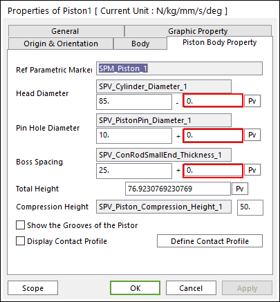
Figure 33.25 Piston property page
The user can make Tolerance between bodies using the value in the red box.
Reference Parametric Marker: Controls the position of piston. It is also the special parametric marker.
Head Diameter, Pin Diameter, Boss Spacing and Compression Height: Are also special parametric values.
The user can modify the parametric value in this section.
These values are enlisted in special parametric value list. The user can check the name of each special parametric value.
Total Height: Is independent values, which are not related with other entities. Refer to the following Figure 33.26.
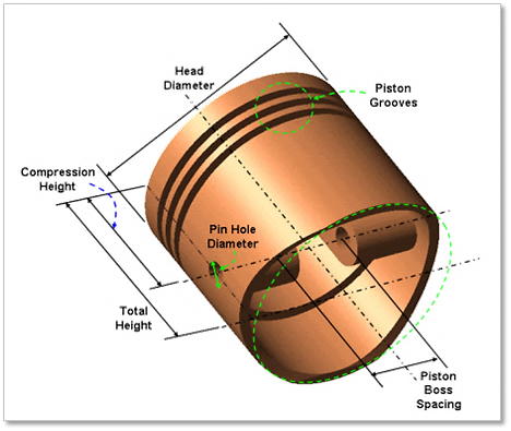
Figure 33.26 Geometrical information of piston
Show the grooves of the piston: Allows seeing the piston grooves as Figure 33.27.
Display Contact Profile: Allows confirming the piston profile associated with the contact between the cylinder and piston.
Define Contact Profile: Allows changing the values to define the piston profile.
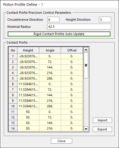
Figure 33.27 Piston Profile Definition dialog box (ex, 5, 2)
To modify the values such as Nominal Radius, Angle and Height, you should change the value (Radius, Angle) related with the circumference direction, and then change the value (Height) related with the height direction.
Enter the values of Circumference Direction / Height Direction (ex, 5, 2) in the above dialog box. And then click Rigid Contact Profile Auto Update. And then can confirm the Piston Profile as a following Figure. The contact Profile is based on SPM_Piston_i (Reference Marker)
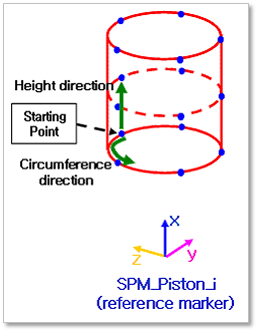
Figure 33.28 An example of the Display Piston Profile of Piston No. 1