20.6.5.4. Discrete Transfer Function
The Discrete Transfer Function block implements the transfer function in terms of the delay operator z.
The system is defined by
\(H(z)=\frac{num(z)}{den(z)} = \frac{num_0z^n+num_1z^{n-1}+...+num_mz^(n-m)}{den_0z^n+den_1z^{n-1}+...+den_n}\)
- where,
- \(num()\) are the coefficients of the numerator\(den()\) are the coefficients of the denominator.
Dialog box
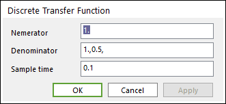
Figure 20.77 Discrete Transfer Function dialog box
Parameter(s) |
Description |
Numerator |
A matrix with multiple rows is specified to generate multiple output signals. |
Denominator |
Enter the row vector of denominator coefficients in descending powers of z. |
Sample time |
Enter the time interval between samples. |
20.6.5.4.1. Example
We can test the filter with the CoLink model shown in the below figure The top Sine block is configured to a frequency of 0.5rad/sec and an amplitude of 1. The lower Sine block is configured to a frequency of 10rad/sec and amplitude of 0.1 and represents the unwanted high-frequency noise. The Discrete Transfer Func block field Numerator contains the value (0.0048, 0.0193, 0.0289, 0.0193, 0.0048) and Denominator contains (1.0000, -2.3695, 2.31240, -1.0547, 0.1874). Sample time for the Sine blocks and Discrete Transfer Func block contains 0.1. The model is configured to use the discrete solver, because there are no continuous states. End time is set to 20. The Mux block creates a vector signal containing the unfiltered input and the filtered output of the Discrete Transfer Func block.
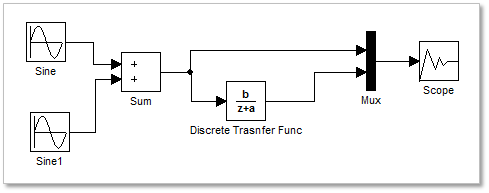
Figure 20.78 colink model
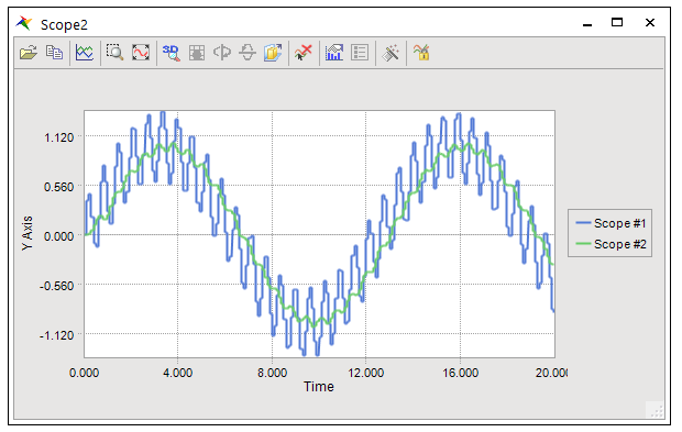
Figure 20.79 A result from scope